Overview:
The "recovery node" is the pyrotechnic controller board designed for LV2. LV2 uses two different parachutes during its descent. The drogue chute opens first. The drouge is a small parachute that stabilizes the rocket but allows it to fall at a fairly high speed in order to minimize the distance the rocket drifts with the wind during descent. For recovery it is desirable that the rocket land close to the launch point.
The descent rate on the drouge chute is too fast for a damage-free landing, so about 500 meters above ground level the drogue chute pulls out the larger main parachute.
The deployment of the parachutes is achieved by pyrotechnic actuators. which are in turn initiated by "Electric Matches". (On LV2 these are Oxral electric matches.) The electric match heads are about the same size as those of ordinary kitchen matches and burn with only slightly more vigor. Their electrical firing energy threshold is about 2mJ.
The job of the recovery node is to provide the firing energy for the electric matches at the critical times, with high reliability.
Related links:
Uplink Ground Equipment:
Older work:
Current Stuff
STATUS
The Recovery Node design phase was completed April 11, 2003.
The prototype was successful after one revison.
The first deployed revision is v1.2 completed August 29th 2004, prior to the Black Rock 2004 launch attempt.
DESIGN GOALS
- Safety
- Reliability
- Low maintenance
- Small size and Low mass
The two towering goals of the recovery system are reliability and safety. Parachute failure probably means complete destruction of our vehicle. At least as significantly, the pyrotechnic actuators are potentially dangerous to our people.
To minimize the danger to people we have firstly designed to minimize the inherent danger in the actuators themselves. Secondly we always handle the devices in such a way as to avoid injury should an accidental activation occur. Our third line of defense involves a system of interlocks in the recovery node.
Reliability is attained by good design. This means good overall design practice, and also minimizing the number of critical components, thorough testing, and some redundancy for low reliability components.
Low required maintenance is a further property that improves reliability, and which is also good for overall performance.
These desirable properties are constrained by the typical PSAS projects goals which seek to minimize the complexity, price, time, weight and size of each component.
SPECIFICATIONS
With the design goals in mind we came up with a short list of must-haves for the recovery node.
- Redundant power source (1 hour independent battery power)
- CAN communication to the flight computer
- Redundant radio communication to the ground on the 2 meter band
- 4 Pyrotechnic initiator circuits for redundant actuators
- Independent failsafe timer
- Mechanical interlock to disable initiator circuits
Each of these specifications descend directly from LV1 hardware but in LV2 each has a slightly different twist. Because it is interesting to understand the reasoning that drives a design, a little history is offered here.
The As-Built specs for v1.2 are:
- Battery, 3.6V Li Ion Polymer, 290mAHr
- Battery Life, 3.86Hr @ 70mA, 2Hr Max to avoid deep-discharge
- Battery Charger, Bulk charge @ 0.5C, full charge in 3Hr
- Capacitive Discharge system, 10μF, 50mJ
A CIRCUIT LEVEL INTRODUCTION
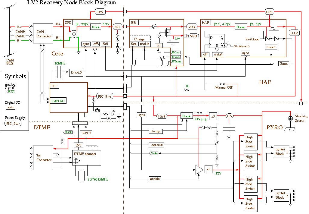
Referring to the block diagram, the circuit is divided into sections, namely the CORE, HAP, DTMF and PYRO sections. The CORE section contains the CAN bus interface which includes the main 14V DC power bus as well as the two wire CAN communications interface. The CORE section has a PIC18F458 microprocessor and a 1.54MHz switching power supply [SPS] to convert the main bus power down to 5 Volts. The intention is to re-use the CORE section for all new LV2 CAN nodes.
To the right of the CORE section is the HAP which stands for High Availability Power supply. The HAP contains another 1.54MHz switching power supply operating in boost mode. This supply provides a 5V output using either the CORE SPS voltage or a single cell rechargeable lithium battery as input. The HAP automatically switches to battery power when the SPS power fails. In the battery backup [BB] section of the HAP there are charging, monitoring and over voltage protection circuits for the lithium battery
At the lower left of the diagram is the DTMF section. This is basically a single chip DTMF-tone to 4-bit-parallel I/O decoder. The DTMF section connects to the 2 meter [2m] radio board which provides an analog audio signal.
PYRO is the recovery node's final section. It contains four 100V igniter switches powered from a common capacitive discharge supply. The 100V [HV] supply is generated using yet another 1.54MHz switching power supply boosting 5V to about 33V which is then run through a voltage tripler into the discharge capacitor. There is a separate voltage tripler to provide the required 12V power supply for the high side switch drivers. For testing there is a disconnectable voltage divider that may be used to measure the HV voltage, or if left connected serves as a bleeder resistor to speed up discharging of the high voltage supply. Lastly there is an externally accessible shorting screw that positively prevents charging of the high voltage supply.
ATTACHMENTS
There are three kinds of file attachments available. The schematic diagrams are provided in source (xfig) format and as PDF files. The printed circuit layout is in eagle format and also includes a schematic diagram, though the eagle schematic is hard to read. The ComponentDesign.pdf file contains detailed, and mostly accurate engineering notes for almost every component in the system.
- Schematics for 03/11/2003 design review
- LV2 Recovery node schematics in xfig (source) format
- LV2 Recovery node schematics in PDF format
- Engineering notes for Recovery node
- PCB layout for Recovery node v.1.0
- PCB layout for Recovery node v.1.1
- PCB layout v.1.2, Final rev. before 2003 launch
Attachments: