LV1/1b Uplink
Overview
The uplink system was flown on both the LV1 and LV1b flights. It is the only method of communicating up to the avionics from the ground, which is why we called it the "uplink". Originally it was intended as a way to remotely fire the pyrotechnic recovery charge from the ground (it's original name was the "Backup Separation System"); later, we added many more features and made it an integral part of the flight sequencing. For example, the Uplink now commands the Flight Computer (FC) to do self tests, arm for launch, etc.
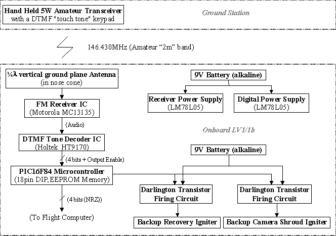
Figure 1: Block Digram of the Uplink System
Ground Station
An amateur 2m band radio with a DTMF ("Touch Tone") keypad was used to send audio DTMF tones to the rocket at 146.430MHz. Note that we chose that particular frequency because it's the Portland, Oregon Amateur TV Coordination Frequency (we also had an ATV transmitter aboard the rocket).
In order to guarantee that we reached the rocket, we used an old 50W Motorola Mocom radio connected to a DTMF generator box. For backup (and communications), our recovery teams located downrange also had 2m amateur hand-held radios. If for some reason the Mocom or DTMF generator failed, then the recovery teams could always command the avionics manually by punching in codes on their radios.
The 146.430MHz signal is picked up by a 1/4 wavelength ground plane antenna located in the nosecone. The signal is demodulated by a Motorola MC13135 FM Receiver IC (http://e-www.motorola.com/brdata/PDFDB/docs/MC13135.pdf). We had to enclose the receiver and power supply (LM78L05) in it's own PCB box since it was very susceptable to being swamped by the other RF transmitters in the avionics. Even bringing out the RSSI lead caused the receiver to be swamped by noise. After careful shielding, the receiver worked with no problems. We even tested it over ~ 7 miles from Council Crest to Powell Butte (see the old meeting notes for the test).
The receiver outputs a 1vpp audio frequency signal, which should contain the DTMF tones and any other communications traffice on that frequency.
DTMF Decoder
The demodulated audio signal is then send to a Holtek HT9170 DTMF decoder chip (http://www.holtek.com/docum/comm/9170.htm). The HT9170 outputs a 4bit DTMF code with an output enable. We found the HT9170 to be very resistant to spurious noise and non-DTMF tones (including low RSSI and high-voice traffice on the band). In fact in extensive testing we never saw a case of the chip spuriously generating a false output signal.
Microcontroller
We used the Microchip PIC16F84 (http://www.microchip.com/download/lit/pline/picmicro/families/16f8x/30430c.pdf), a small (18pin DIP) 4MHz RISC microcontroller, to decode the DTMF nibble and output enable bit from the Holtek decoder. The PIC read in the nibble every time the enable line was lowered and used the nibble received in a state machine to determine what to do. The state machine screened for the password and command while allowing for repetitions in the nibble (we assumed long dropouts would look like repeated key presses).
We required a simple password - a "#" followed by a "*" - and then a command 0 - 9. Only three commands (numbers) directly applied to the PIC - fire the recovery igniter, fire the camera shroud igniter, and reset the igniter outputs. The igniter circuitry uses a simple NPN transistor driving a PNP Darlington in a TO220 case to fire the igniters. The igniters used were "Estes" brand igniters, but substantially modified to increase reliability.
Sending the DTMF data to the FC
The microcontroller also sent the DTMF nibble - no matter what it received - to the Flight Computer(FC) in a non-return-to-zero (NRZ) format. This way the password and command structure could be different for the FC. We decided to keep the same password (#*) and then used the rest of the 0-9 commands for various FC tasks. We used "9" to indicate an escape code that another digit was coming, which allowed us to increase the number of flight computer commands. We called these "primary" (#* + command) DTMF commands and "secondary" DTMF commands (#* + 9 + command).