PSAS Inertial Measurement Units (IMUs)
See also our sensor comparison chart
We've built two IMUs so far. The first is almost not worth mentioning. The second is great, but represents what happens when you have to build something really complicated really quickly. We can't WAIT to do the third generation IMU - slowly and carefully ;)
LV1 IMU
| First Flight | April 11, 1999 |
| Accelerometers | 3x Analog Devices ADXL50 |
| Gyroscopes | 3x Tokin CG-16DO ceramic rate gyroscopes |
| Calibration | No calibration except initial values before launch |
| Bandwidth | Sensors bandwidth limited to 500Hz (A) and 100Hz (G) Sensors sampled at 1.00KHz |
| DSP | Data low pass filtered to 12Hz for transmission down 2.4kbps downlink |
| Final data format | Raw data values of X,Y,Z acceleration and a,b,g angular velocities |
LV1b IMU
| First Flight | Spring 2000 |
| Accelerometers | Analog Devices ADXL202 and ADXL 250 |
| Gyroscopes | 3x Tokin CG-16DO ceramic rate gyroscopes |
| Calibration | Simple 1g and constant rotation calibrations |
| Bandwidth | Sensors bandwidth limited to 1kHz (A) and 100Hz (G) Sensors sampled at 2.50KHz (A) and 833Hz (G) |
| DSP | Data low-pass filtered to 100Hz for position calculation |
| Final data format | X,Y,Z,a,b,q position and attitude values |
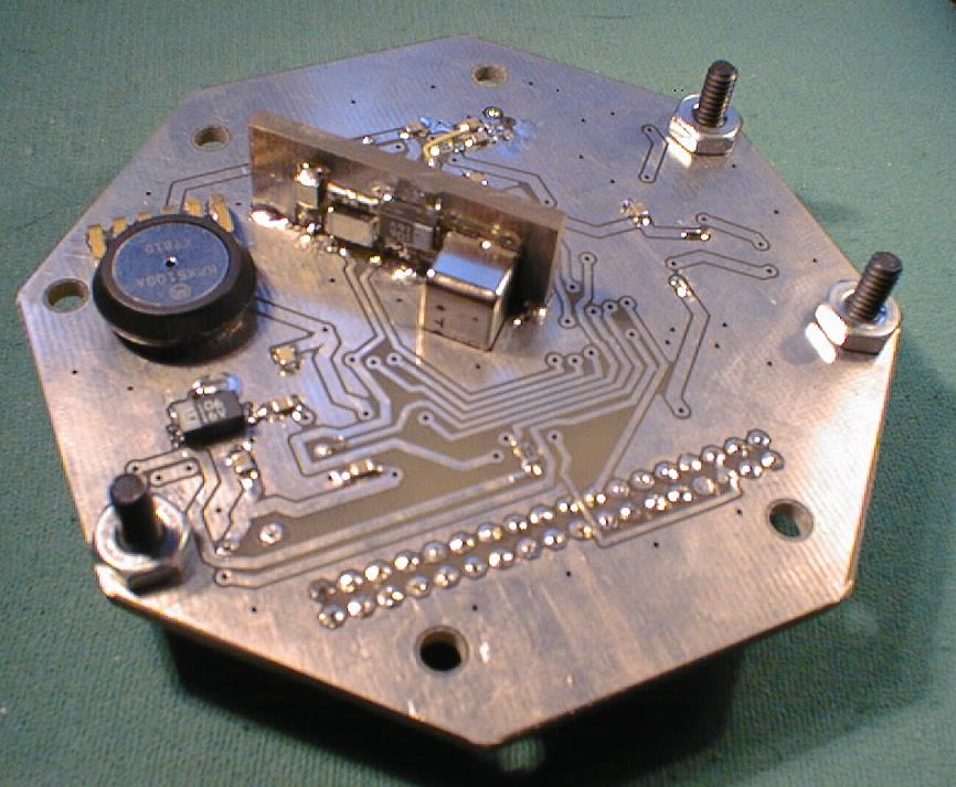
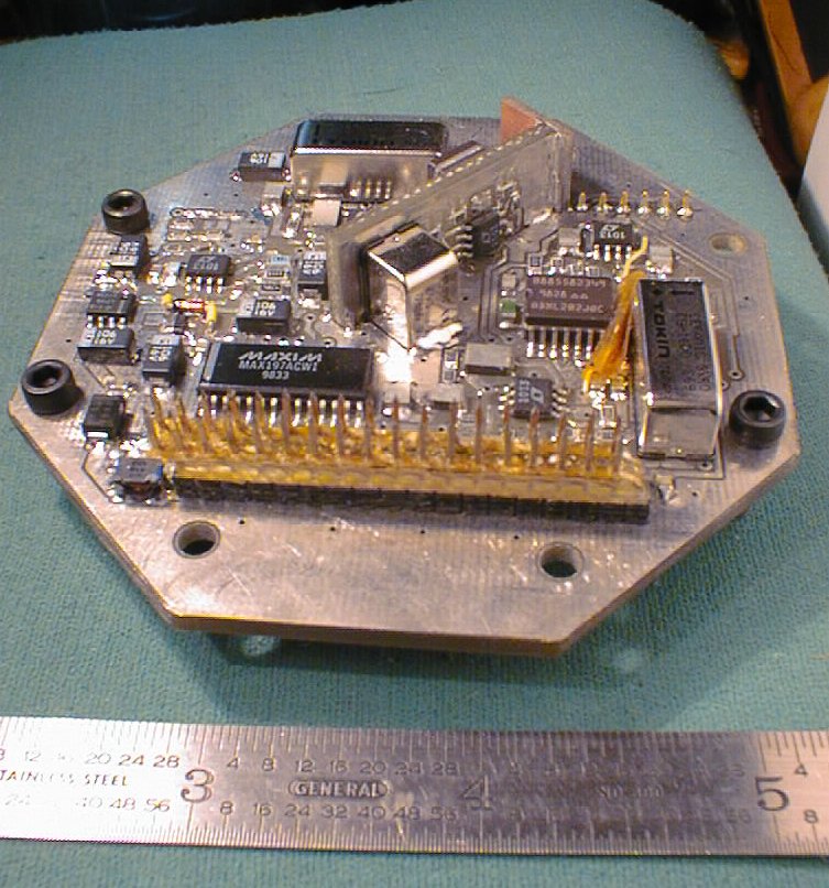
Here are a few pictures of the IMU, which was meant to mount directly with the Lv1b Flight computer:


Current Tasks:
- Calibrating the LV1b IMU: ImuCalibrationLV1b
- Firmware for the IMU CAN Node: CanNodeFirmwareImu
- Markus' final new IMU project report: WhitePaperLv2IMU
"Q" acceleration axis
In our current IMU we make some redundant acceleration measurements. We want to use the extra data to refine our estimates and increase sensor reliability. Here is a first cut at integrating the x, y, and "q" axis accelerometer data.
- xyq.pdf: Best estimates for X and Y given x, y, and q
Raw Data
- data: Data from the 1999/04/11 flight of LV1 with the LV1 IMU
- data: Data from the 2000/10/07 flight of LV1b with the LV1b IMU and GPS:
Inertial Sensors
Our current list of inertial sensors, with our own incomprehensable comments:
Various Commercial 6DOF IMUs:
- Crossbow - FOG/Acc/6dof D/A IMUs (Particularly interesting is MicroNAV):
http://www.xbow.com/ - Honeywell INS Homepage: http://www.tspi.elan.af.mil/
- USAF TSPI Homepage: http://www.tspi.elan.af.mil/
- Litef FOGs and IMUs: http://www.litef.com/
- XSens: http://www.xsens.com/
- http://www.rotomotion.com/
- http://www.cloudcaptech.com/