LV2 CAN Nodes
LV2 consists of a main processor - the "Flight Computer" which is a 586 PC-104 board - and a dozen tiny little boards strung out on the CAN bus. These dozens of little boards are each run by a small microcontroller (currently the PIC18F458) and perform all of the sensing and actuation for the vehicle.
Since each of the boards has the same microcontroller, we've decided to break the nodes up into virtual "sections". Each section is a schematic and layout all to itself; using a common interconnect pattern, these layouts are then laid next to each other by a Gerber editor application. It's a clever way to eek some professional quality features from a shareware program (EAGLE).
CAN Node "Sections":
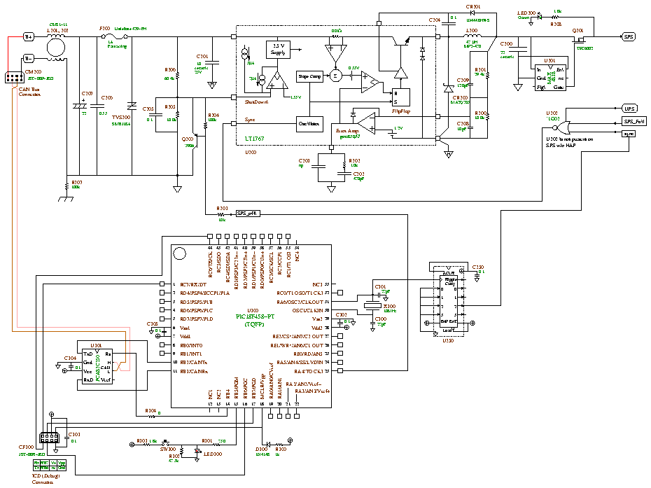
| CanNodeSectionProcessor | The section with the PIC18F458, 12 to 5V switching power supply, oscillator, an optional Vref and ICD plug-in. |
| ?CanNodeSectionInterface | The section with the CAN and power connectors, all still TBD. |
| ?CanNodeSectionMechanical | The section with the space for fasteners and possibly a card cage - all TBD. |
Can Node "Application" Sections:
| CanNodeSectionAppPyro | The application section with the pyrotechnic igniter firing circuits, amateur 2m radio receiver with DTMF decoder, and Li backup power supply. |
| CanNodeSectionAppPower | The application section with a Smart Battery System (SBS) Level 2 charger, various power devices, and Umbilical cord connector. |
| InertialMeasurementUnit | |
| GlobalPositioningSystem | |
| MagnetometerBoard | |
| MiscCanNode | |
| AmateurTelevision | |
| BatteryPack |
Misc:
ICD2 to CAN Node cabling information
Used PIC18F458 Pins
The "next generation" PIC nodes are converging to a single design, with a neat little CAN connector, switched power supply (SPS) and for critical nodes, a highly-available power supply (HAP). Also, all nodes must have an oscillator, ICD2 pins, MCLR, etc.
| Name | Pin | Type | Modules | Description |
|---|---|---|---|---|
| MCLR | 18 | in | ALL | Master reset |
| OSC1 | 30 | in | ALL | 10MHz crystal input |
| OSC2 | 31 | out | ALL | 10MHz crystal output |
| RA0 | 19 | in (A) | HAP | "HAPBCurr" - HAP battery current measurement |
| RA1 | 20 | in (A) | HAP | "HAPBVolt" - HAP battery voltage measurement |
| RA2 | 21 | in (A) | HAP | "HAPBTemp" - HAP battery temperature |
| RA4 | 23 | OC out | SPS | "SPSOFF\" - Shuts down SPS. |
| RB2 | 10 | out | ALL | CAN TX |
| RB3 | 11 | in | ALL | CAN RX |
| RB4 | 14 | out | ALL | CAN transciever (MCP2551) slope/reset |
| RB5 | 15 | i/o | ALL | LED/switch combo ("omnibutton", Error LED, etc) |
| RB6 | 16 | out | ALL | ICD2 (PGC) - SET TO OUTPUT so it doesn't fload wo/ICD2 |
| RB7 | 17 | out | ALL | ICD2 (PGD) - SET TO OUTPUT so it doesn't fload wo/ICD2 |
| RE0 | 25 | out | HAP | "HAPTrickle" - Enables trickle charging of HAP battery |
| RE1 | 26 | our | HAP | "HAPFast" - Enables fast charging of HAP battery (Overrides trickle charging) |
| RE2 | 27 | out | HAP | "HAP_Off" - Power down HAP |
in = digital input, out = digital output, oc = open collector, in (A) = analog input, HAP = Highly Available Power supply, SPS = Switching Power Supply.
There are some pins which usually get used for the same thing: RB0/1 are good for edge-triggered interrupts, RC6/7 are the onboard UART pins, etc.