Spin Can Background
During our first experiments with roll control, we learned that the control canards have a tendency to produce adverse roll (a rolling moment that is unintentionally applied to the airframe). Further, when the canards are sufficiently smaller than the stabilizing fins, a roll command sent to the canards can actually result in a roll in the opposite direction due to the aerodynamic interaction of the canards with the fins.
One method of eliminating the adverse roll problem is to de-couple the stabilizing fins in the roll axis. This can be accomplished by attaching the fin can (a hollow cylindrical section of the airframe that supports the fins, similar to a long 'can') to a special bearing so that it is completely attached to the airframe, yet allowed to spin freely about the rockets' z-axis. Basically, this is a 'fin can' that 'spins', or 'spin-can'.
This page contains documentation of the design and construction of the 'spin-can'.
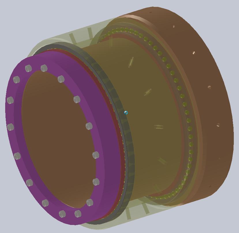
Design Images
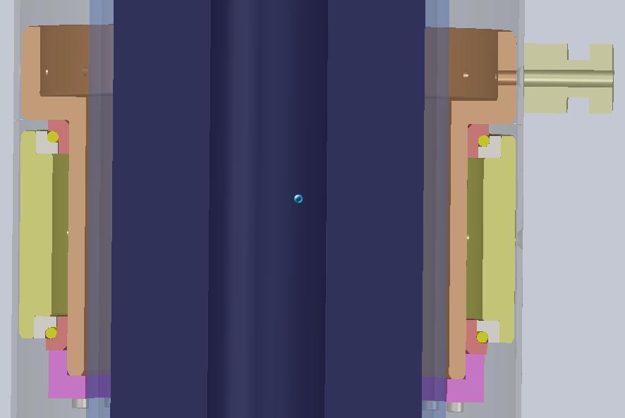
Construction
Bearings
Large, lightweight bearings of this type are expensive ($500 each). We decided to make our own. We chose 4340 steel because it's available, reasonably priced, and we can work with it to get nearly the right hardness for a bearing (Rockwell C58). We expected C51 hardness out of our races based on heat treating data available on the web. Lab testing found our hardness at Rockwell C52.2; basically right on target.
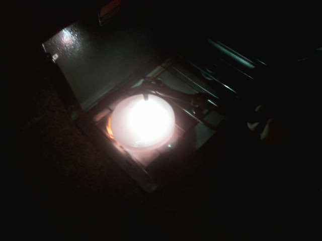
Annealing the steel
Prior to machining, it's a good idea to get the steel into a soft (annealed) state. This way, the machining operations will be easier and the tools will last longer.
Annealing for this type of steel requires heating to over 900 C, then allowing the steel to cool on it's own back to room temperature.
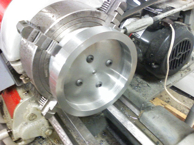
Rough machining
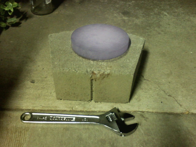
Heat treating
To harden the steel so it will work as a bearing race, we heat the steel to the austenic temperature range (900+ C), then quench the steel in an oil bath. Finally, the steel is tempered in an oven at 204 C for a couple of hours.
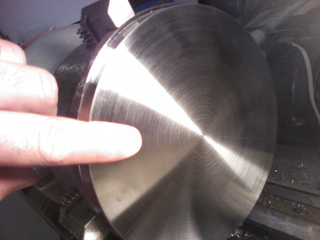
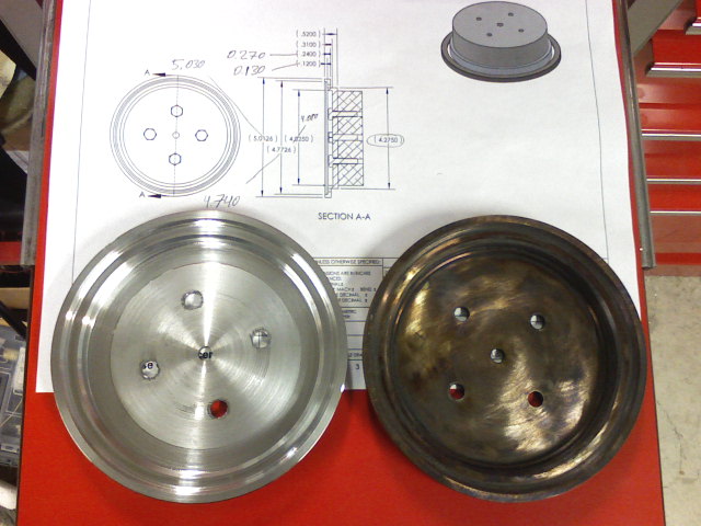
This process produced a very hard steel that is capable of acting as a bearing race. Machining tests confirm the steel is hard enough to make it impossible to machine using carbide cutters with TiN coatings (RC52.2 in lab tests).
The following photo shows the annealed, machined material on the left; and the hardened, tempered material on the right.
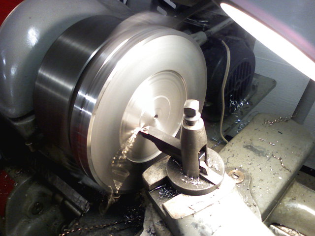
Finish grinding
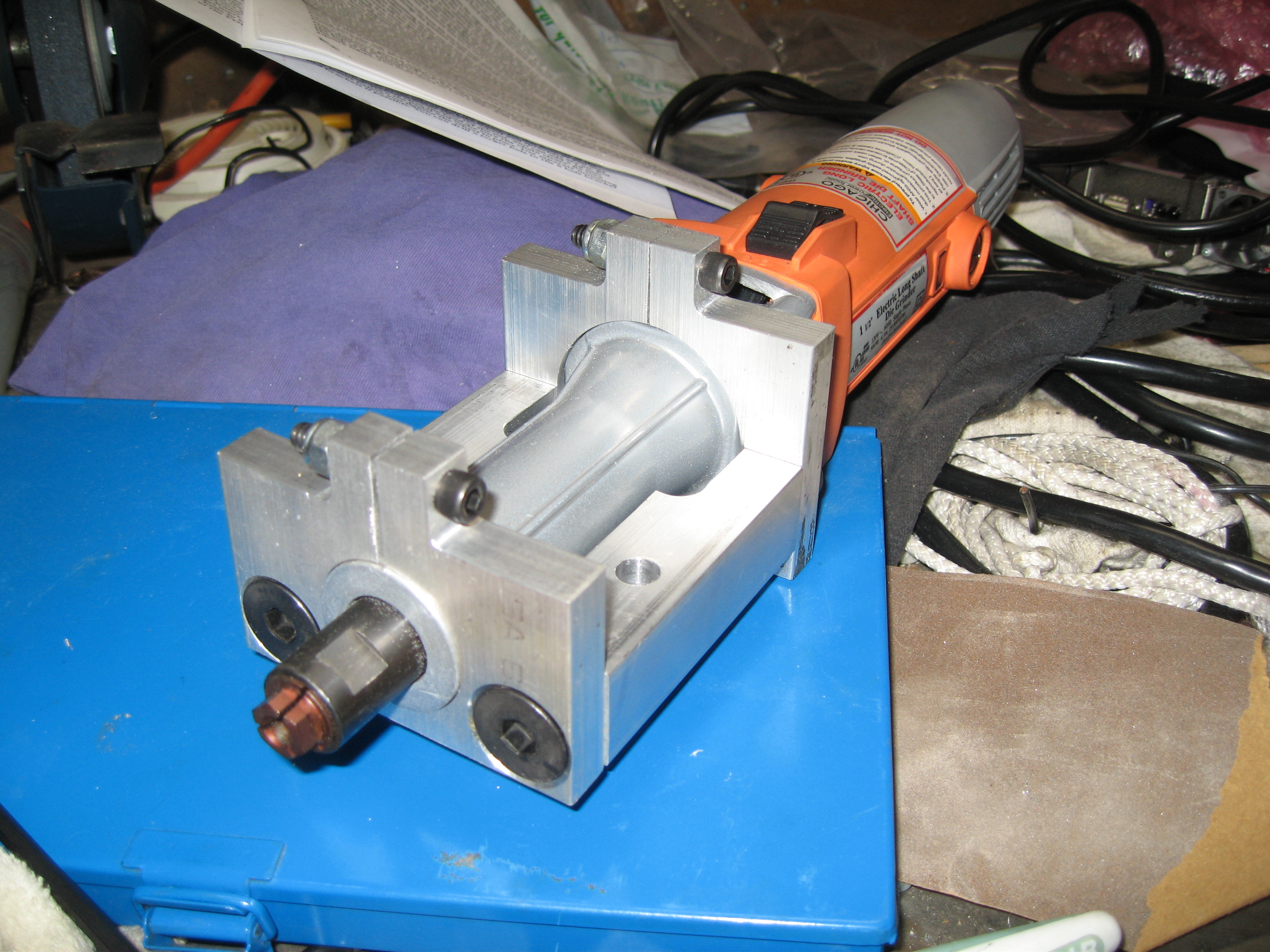
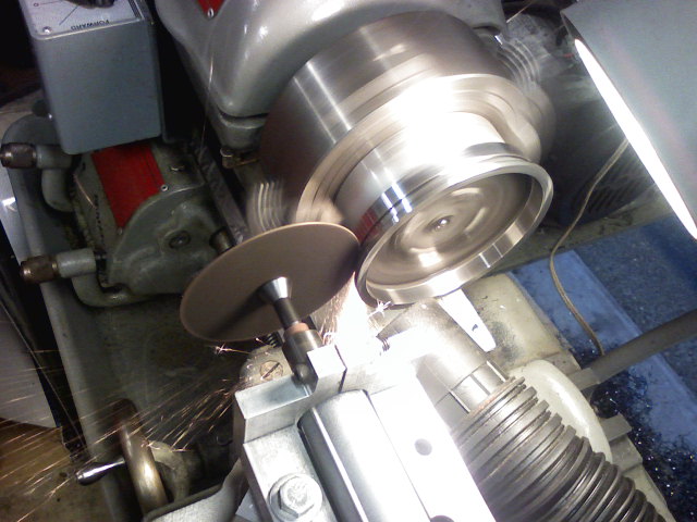
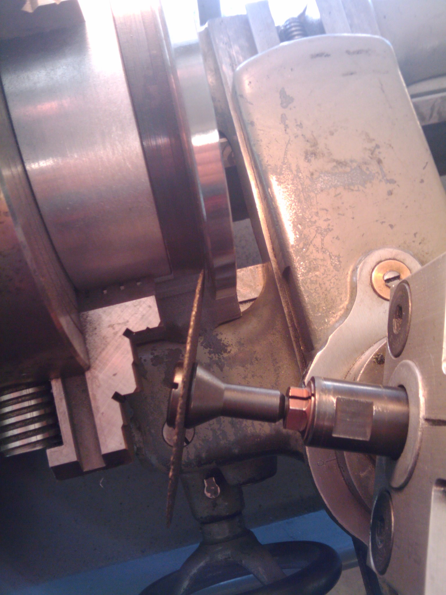
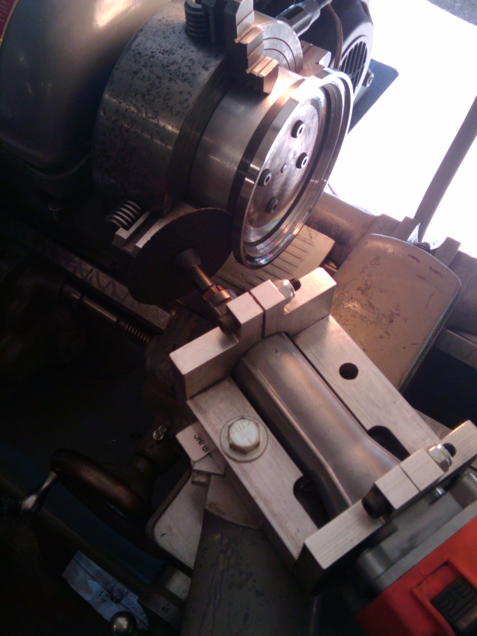
To produce a bearing with reasonable accuracy using hardened steel, lathe cutting tools are not hard enough to cut the material. Further, standard cutters produce a relatively rough surface when compared with bearing race surfaces. Instead, finish grinding is required to produce a smooth, accurate and hard surface for the rolling elements of the bearing. A tool-post grinder is a lathe mounted device used to produce these smooth surfaces.
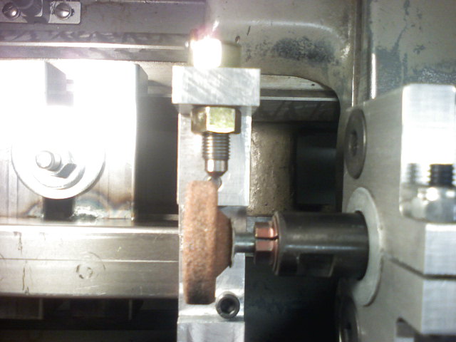
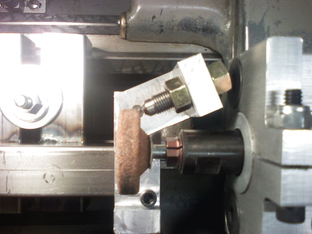
The following photo shows a tool-post grinder made from an inexpensive electric die-grinder.
To produce the desired finish on the steel with controlled radii, we built a stone dressing tool for the toolpost grinder. The stone dressing tool uses a 3/8 Carat diamond mounted in a rigid pivot fixture. This particular dressing tool will dress all sides of the stone, as well as provide adjustable radii by pivoting the dressing diamond around the corner of the grinding stone.
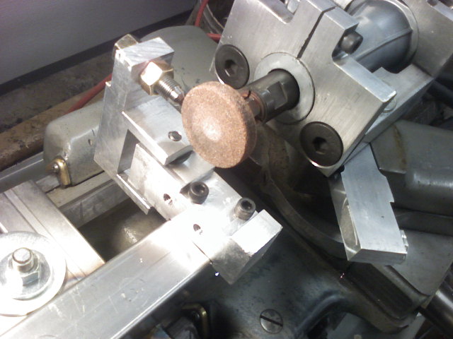
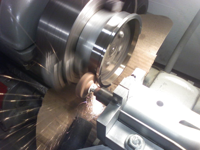
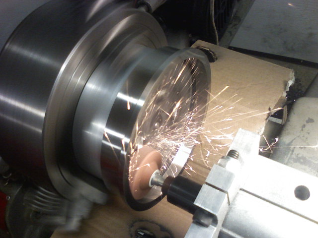
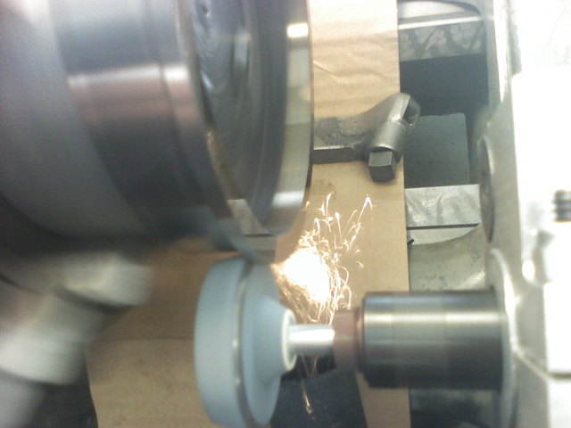
The grinder in action on the bearing inner race:
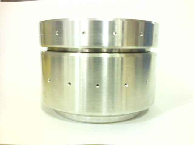
Finished bearing races
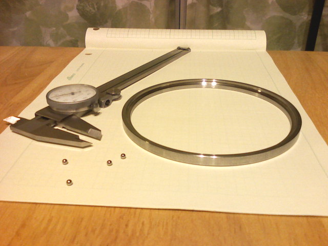
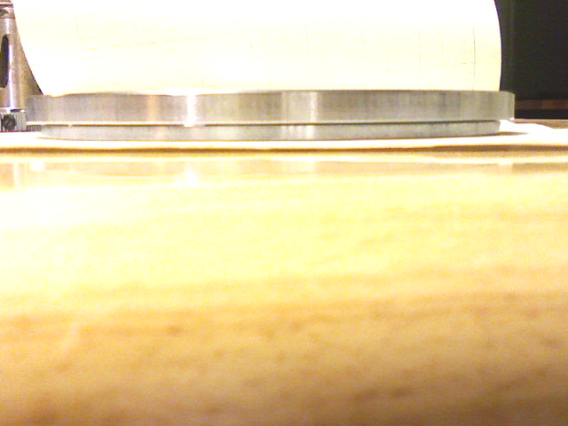
The inner race:
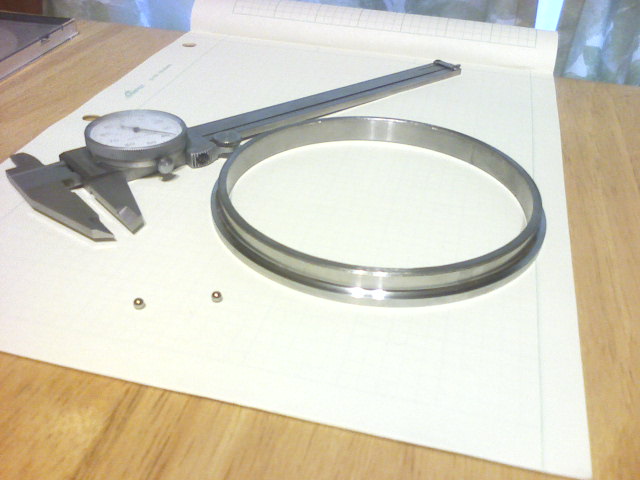
The outer race:
The assembed bearing races and balls:

A final note on making bearings... The trick to this bearing race construction project is to design the race so that all important bearing surfaces can be ground without removing the race from the machine. The final operation is to cut the race from the parent material, with this last cut being a non critical dimension. This was difficult in this project because the bearing has been finish hardened, and does not cut easily. While the process was successful, the cutting was very difficult. The next time we attempt this, we will likely design a fixture which holds the race during grinding, and finish the cutting operations before hardening.
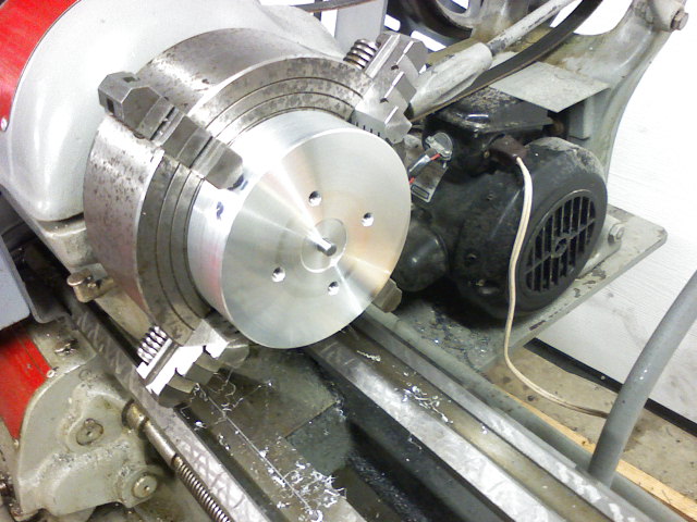
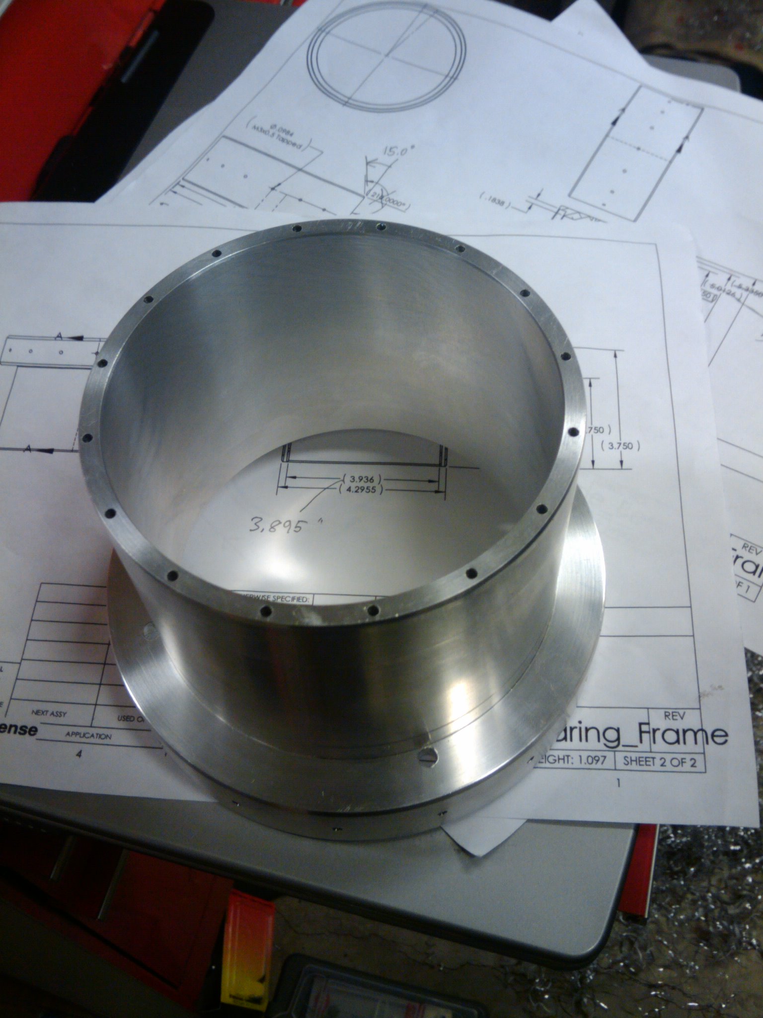
Inner Race Frame
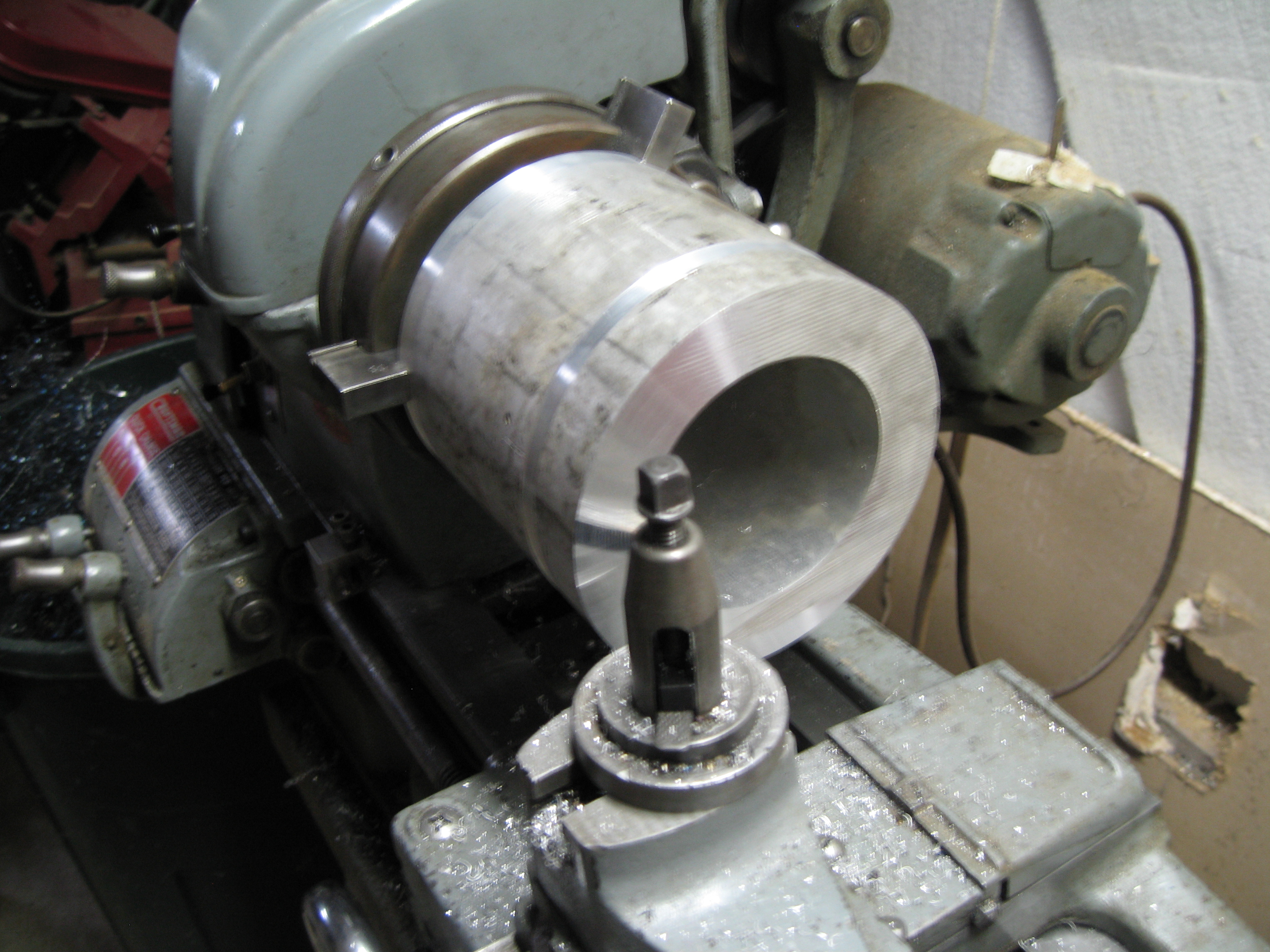
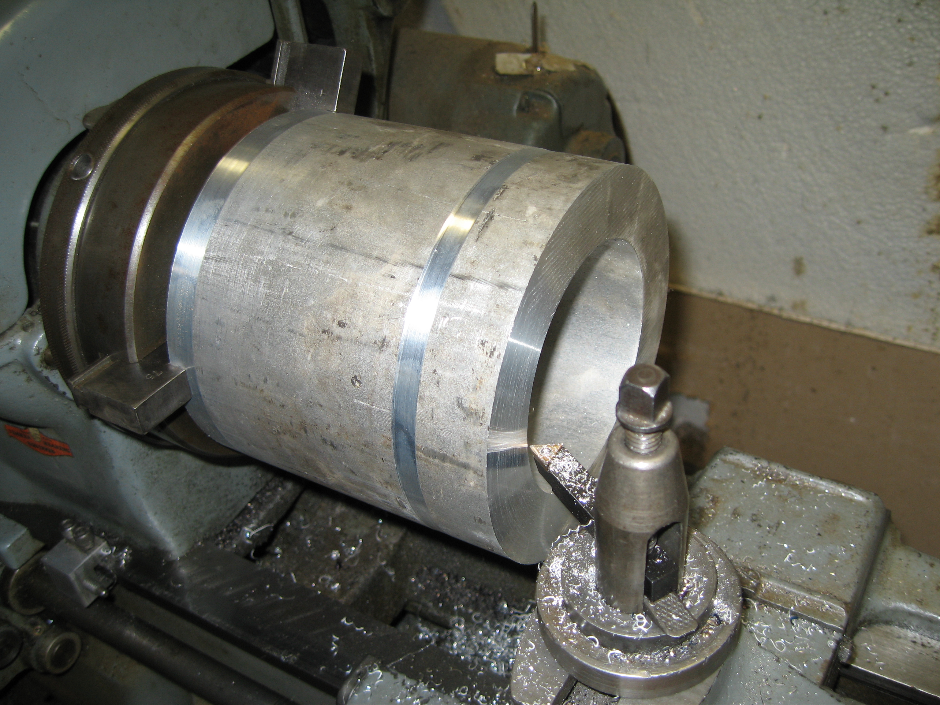
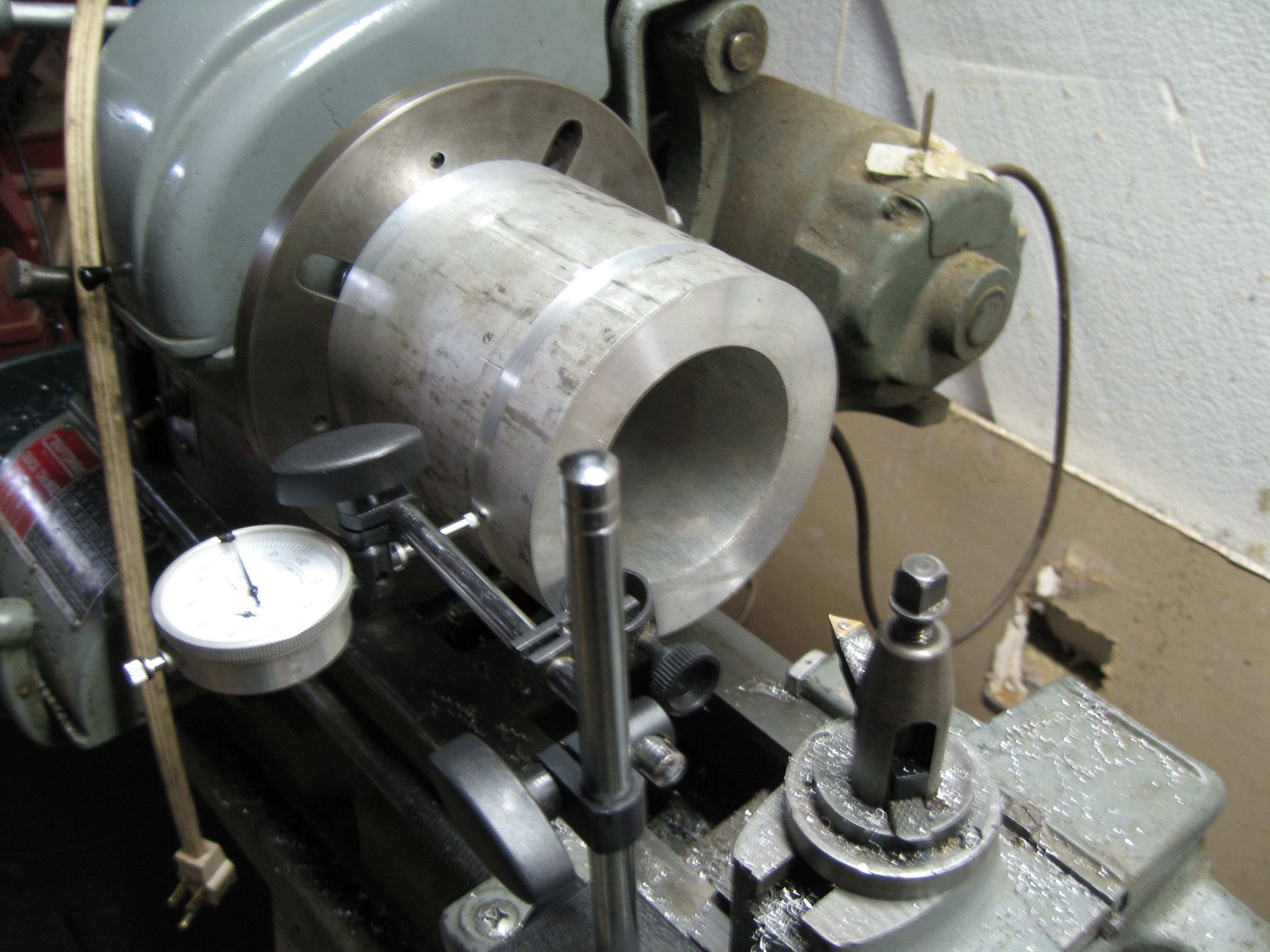
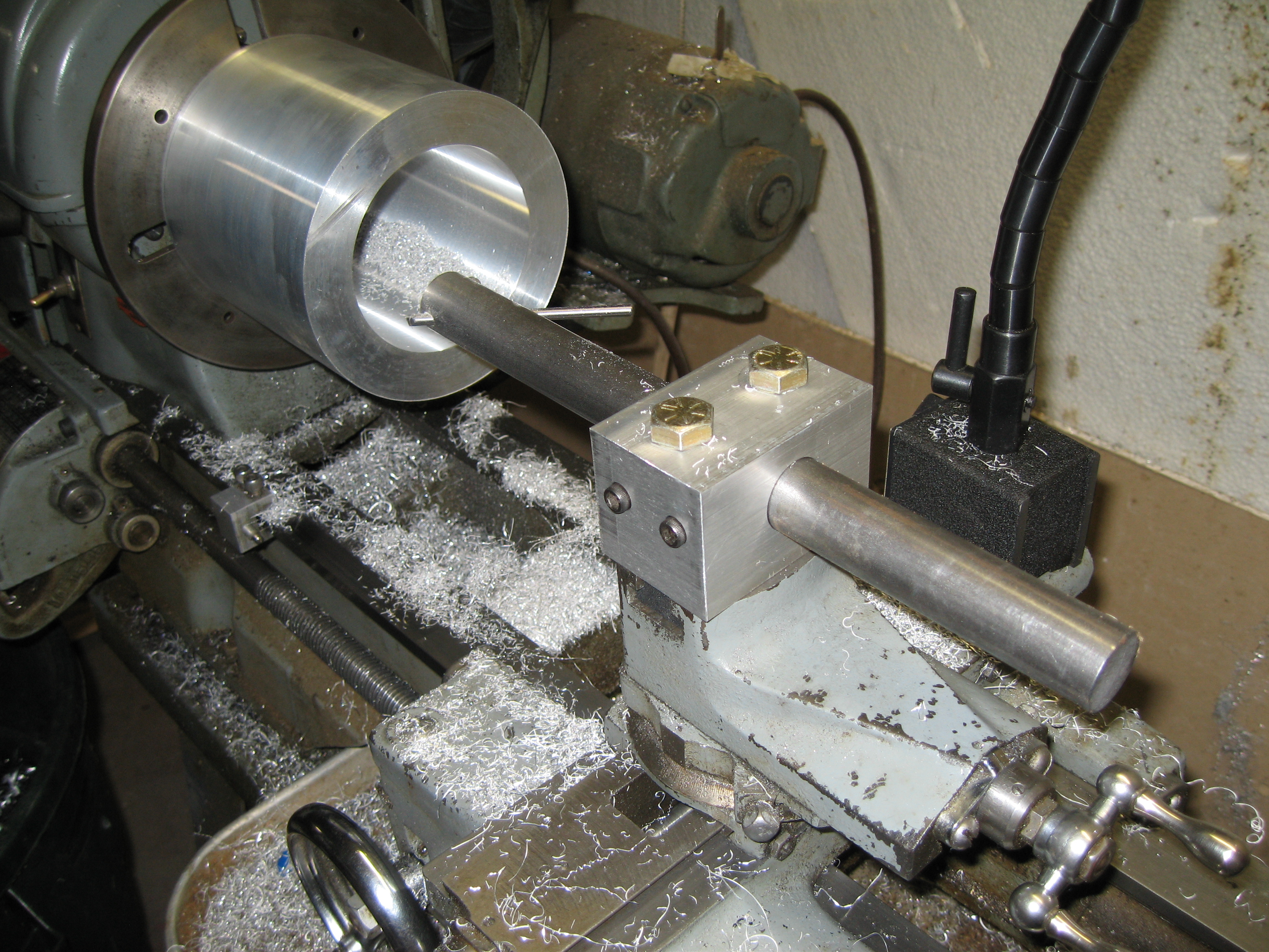
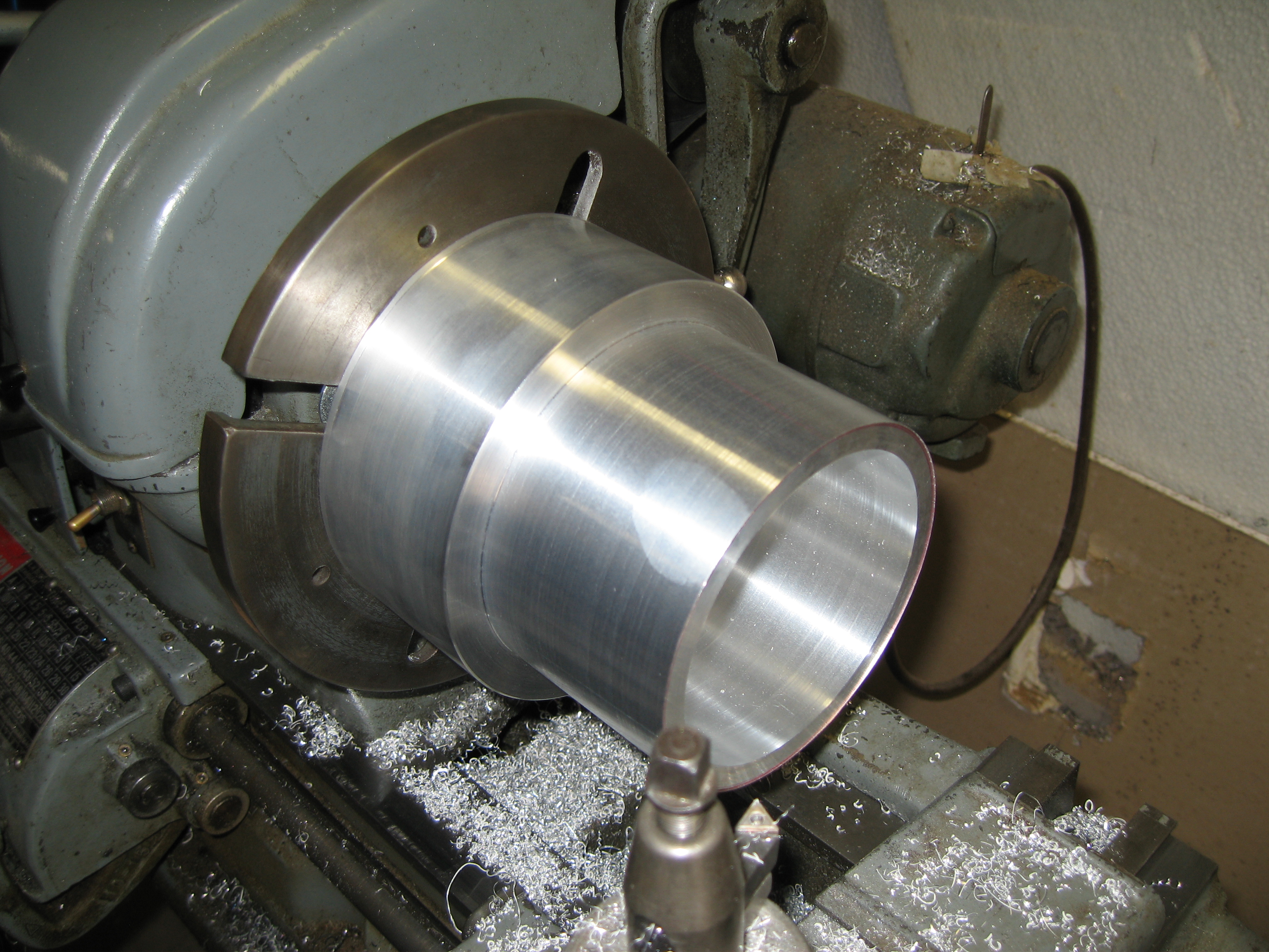
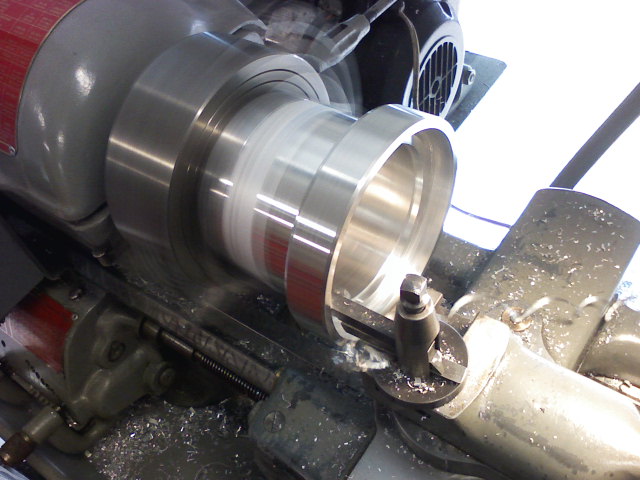
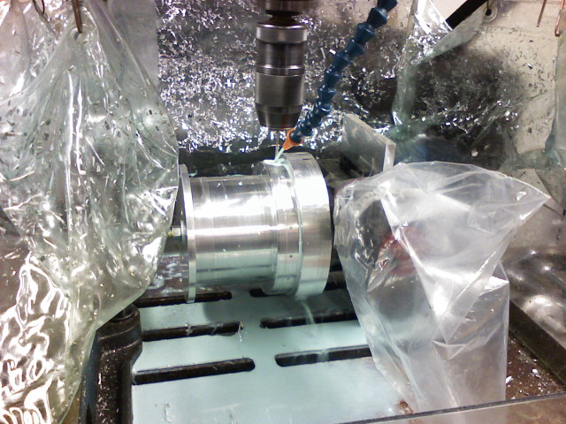
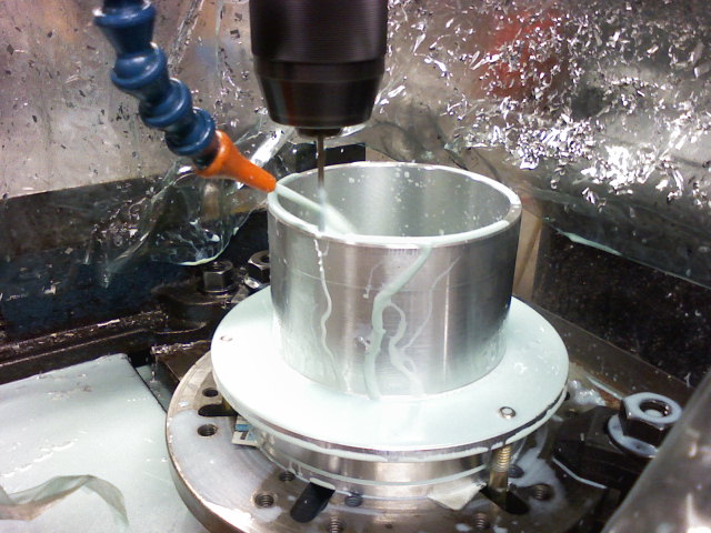
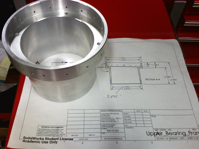
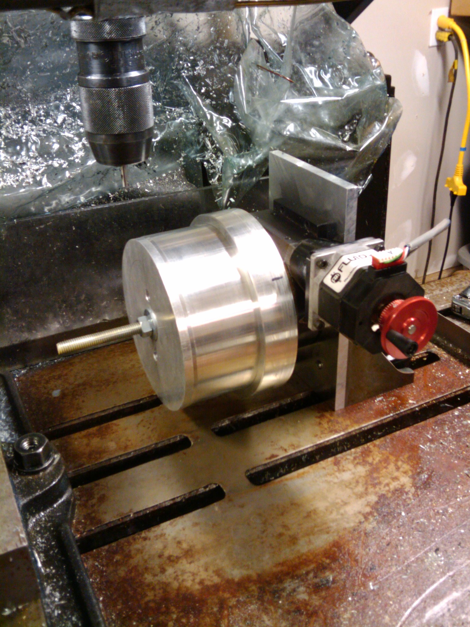
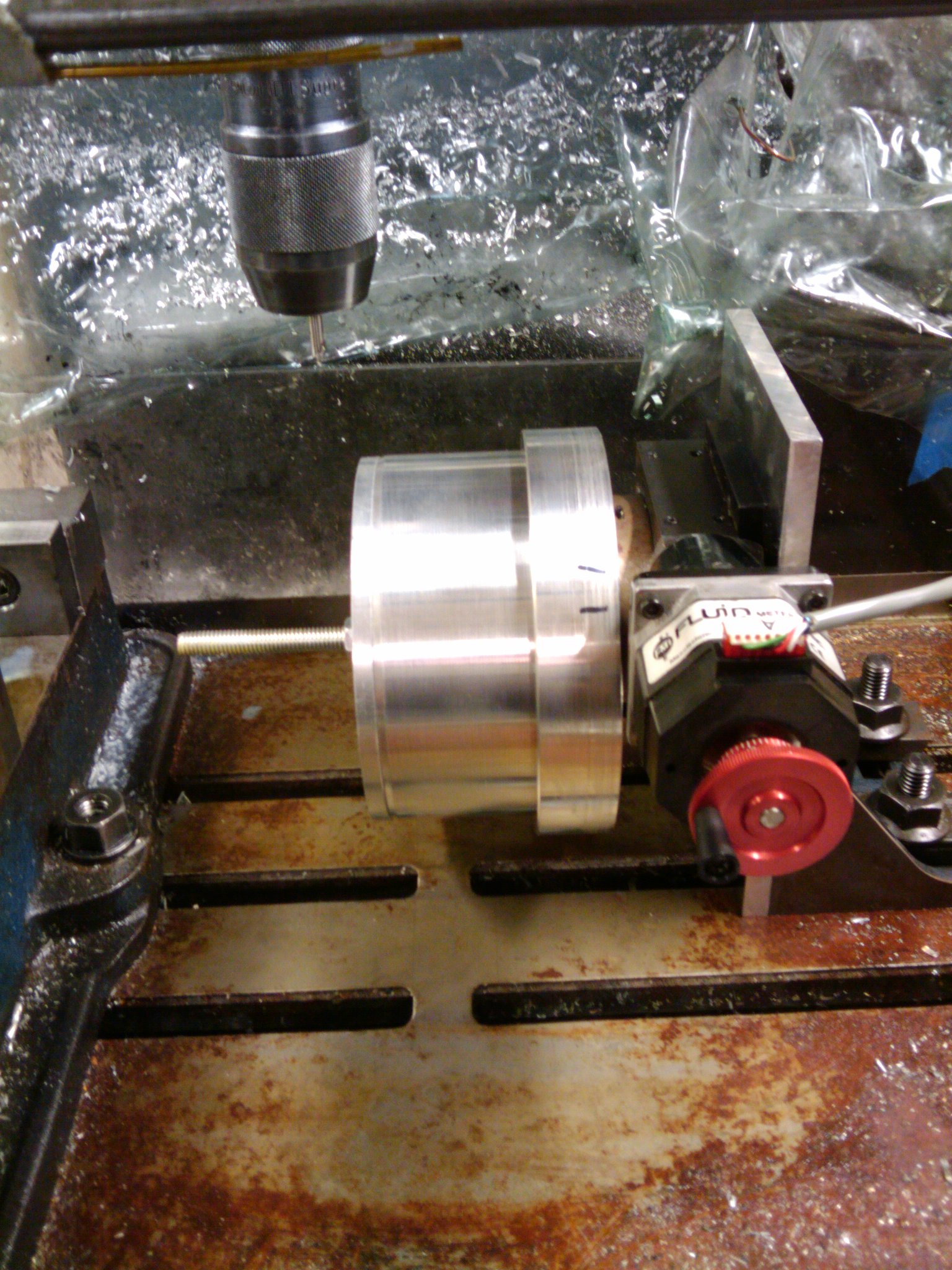
The raw material for the inner race frame came as extruded 6061-T6 aluminum tube. We cleaned up a few of the faces, drilled and tapped (4) 3/8-16 bolt holes in one end, mounted it to the lathe drive plate and centered it, had to make a boring bar that was long enough and rigid enough to get 4.5" down the center of the tube.
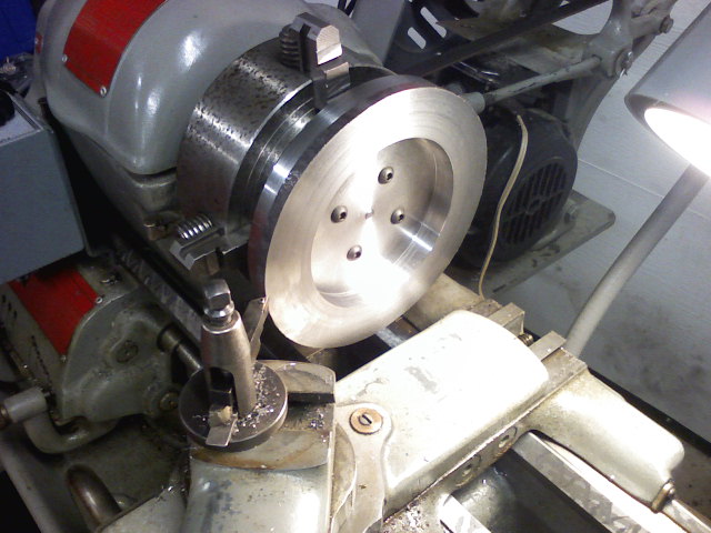
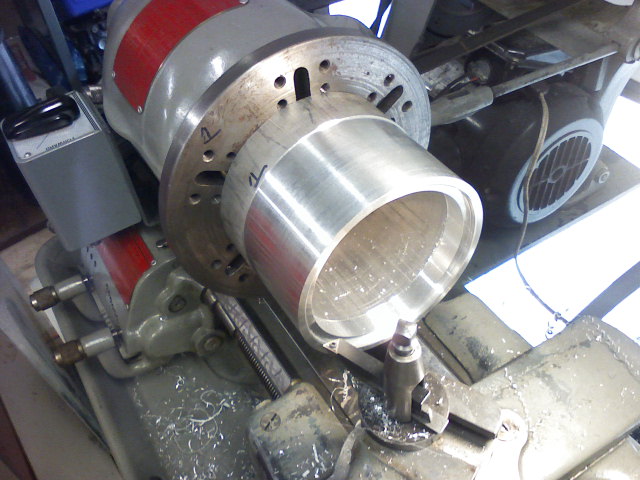
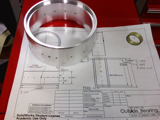
Outer Race Frame
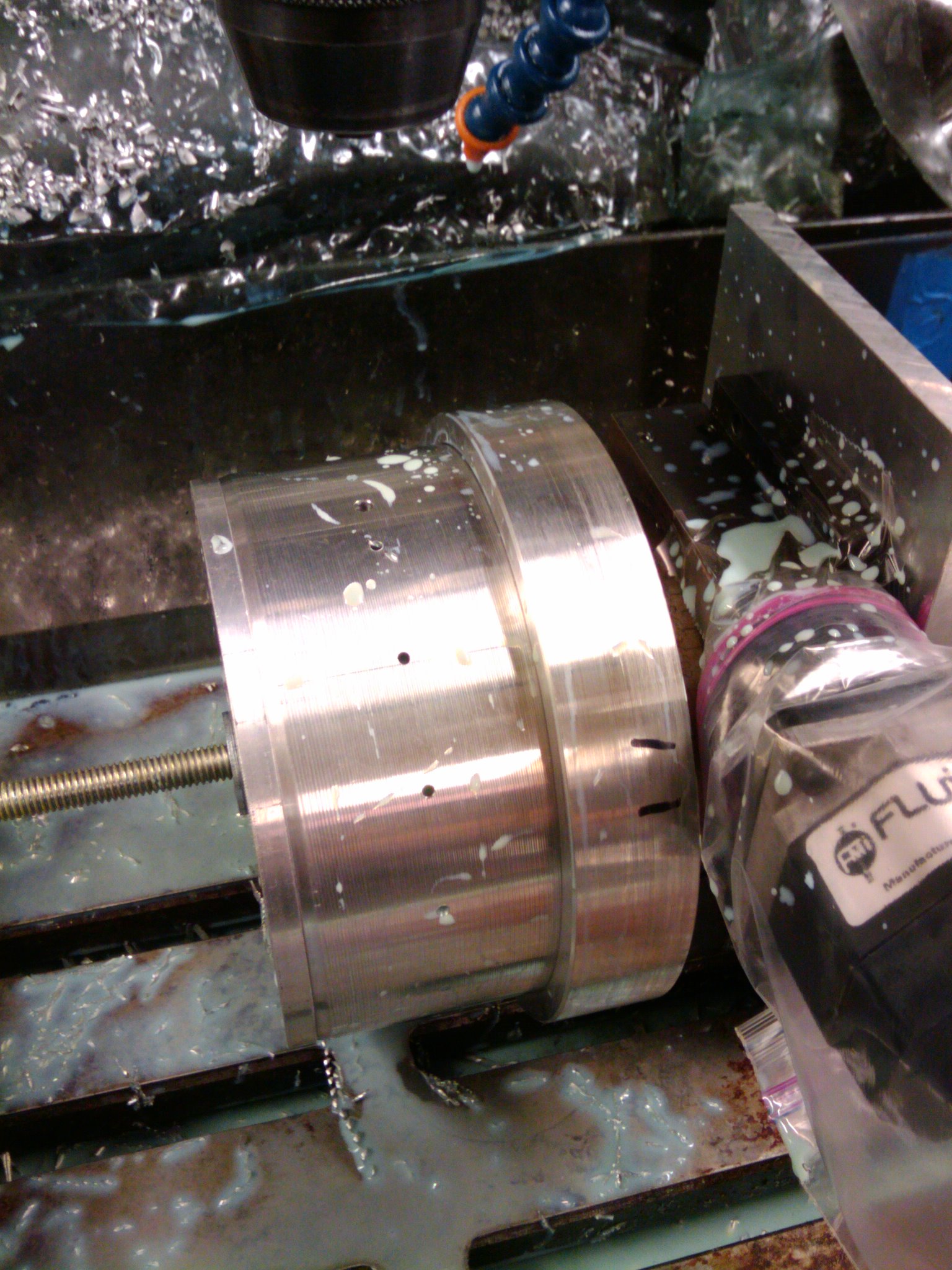
The outer race frame was constructed in a similar manner to the inner race frame. (3) 5/16-18 bolts attach a length of extruded 6061-T6 aluminum tube to the lathe drive plate.
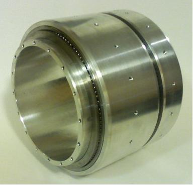
Assembly
Assembly of the spin can bearing was fairly simple. The parts were cleaned and laid out prior to assembly. We used heat to expand the outside parts, and cold to contract the inside parts. This practice makes assembling interference fit parts very simple. Adding the ball bearings can be tedious, but it went smoothly.
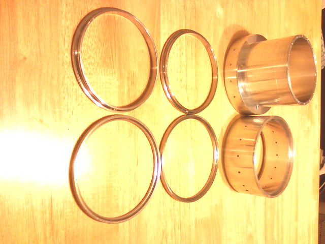
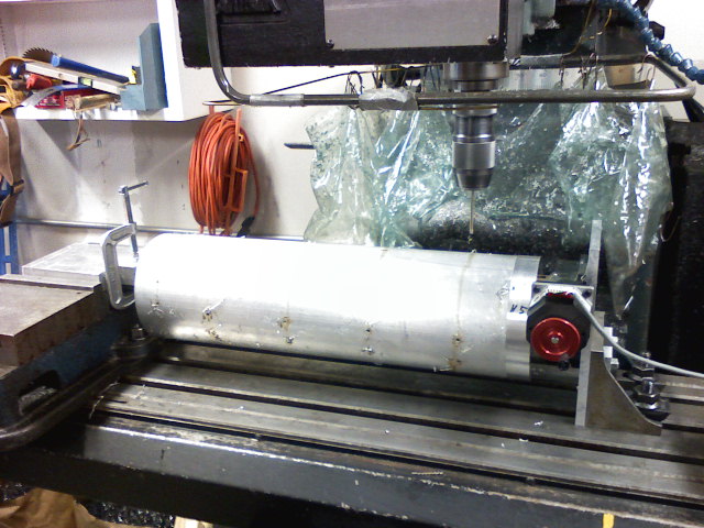
Fairings
Custom motor fairings were required for the new spin-can. The overall fin position was to remain the same, but the fin can would use three fins instead of four, and the spin-can bearing would connect the motor fairing and the fin can. Motor fairings were constructed in a manner very similar to how they were in the past. The following photos show the fairings being drilled for mounting holes:
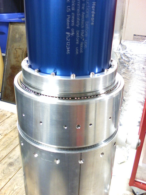
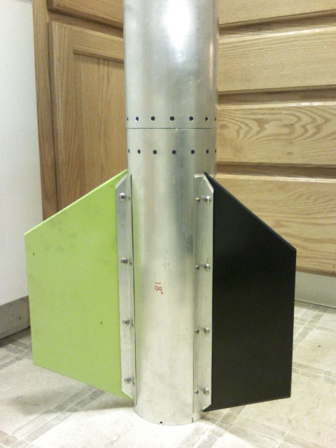
In The Rocket
Project Complete!
Test fitting the bearing in the rocket frame, and the final assembly with fins: