A&TB Battery Pack for LV2
| Up: | AvionicsPowerSystemLv2 |
|---|---|
| Xref: | AandTBatteriesLv2, AvionicsPowerSystemLv2, Lv2PowerUsage |
Coulomb Counter
LTC4150: http://www.linear.com/pdf/4150fs.pdf
We'd love a smart battery to tell us the charge on the batteries. We can get a pretty good aproximation by using our own "coulomb counter" or "fuel gauge" IC.
It's exactly what we want - it gives a pulse every n coulumbs of charge in/out of the battery. But, it only goes to 8.5V! After tearing our hair out for a while, we decided we could put it across the bottom two "parallel cell packs" in the battery pack and just not worry about it. Sure, it'll draw a maximum of 115 uA off of the lower two batteries and not the top two, but quoting a well known battery pundit: "During discharge @ C/1 the extra draw from the lower two cells is ~115uA * 3600s = 414mC. The pack capacity is ~4A * 3600s 14.4kC. The imbalance is 28.75E-6 of pack capacity." So at 30 ppm imbalance, we just don't care. So we can use the IC, even though it won't go across the whole pack.
There are other chips, but we hate low side current shunts and the I^2 bus (E.g., http://www.maxim-ic.com/quick_view2.cfm?qv_pk=1793&ln= ). (Actually certain well known battery pundits don't mind low side shunts. They do hate the I2C bus though. ; )
Calculating the LTC4150's shunt resistor, Rs:
Rs = 50m V / Imax = 50 mV / 5 A = 0.01 Ohm
The 5 A needs to be justified a bit; in the Power consumption in LV2 we draw about 2.8 A. I figure an over estimate of roughly two is right; we may add lots more junk to the rocket, and more importantly, we're charging the battery pack at about 1C which is about 4 A.... so 5 A seems pretty reasonable. It also gives us a nice round shunt resistor (10 milliohms). At 5 A, that's a power rating of (5 A)^2 * 0.01 ohm * = 250 mW.
- Oh oh oh I love this: a four terminal shunt resistor, Ohmite 1% 3W: Digikey CS3FR010-ND $10.23 (!)
- Else this weird package Ohmite SMD 1% 1W power resistor: Digikey RW1S0BAR010FBK-ND $2.53
- Else Panasonic 2512 1W 1% (+/- 100 ppm tempco): Digikey P10MMCT-ND $8.16/10
Calculating the filter Capacitors:
They say use a cermaic 4.7uF and don't give much justification for it; bigger is, of course, better, but since "A 10nA leakage is roughly equivalent to the input offset error of the integrator" the leakage needs to be dealt with. I'd like to check on the Panasonic Multilayer Ceramic Chip Caps (MLCC) - http://www.panasonic.com/industrial/components/mlcc_page.htm - but so far I can't find any kind of leakage info. In particular, the 1206 X5R 25V 10uF part (Digikey PCC2326CT-ND)... I'd go with that until we find the leakage current sucks.
The Error Budget
- Gvf = Voltage to Frequency Gain which is set in the chip: 31.8 (min)/ 32.55 (typ)/ 33.3 (max) Hz/V which means we have 1.5/32.55 = 4.6% max error
- Gvf varies with VDD like 0 - 0.5 %/V with ~ 5.2 V baseline (see Voltage to Frequency Gain vs Supply Voltage graph) which for 8.5V and 2.5V is 1.7 %and 1.4 % respectively.
- Gvf varies with temp like -0.03 to 0.03 %/deg C from 25 deg C (see Voltage to Frequency Gain vs Temperature graph) so for a 20 deg C temperature excursion that's 0.6%
- Integral Nonlinearity -0.4 to 0.4 %/full scale
That gives a total extreme (thus unlikely) error of 4.6% + 1.7% + 0.6% + 0.4% = 7.3 % error. But we expect to be able to calibrate out the Gvf error to near zero (ha!) and the voltage effects during flight should be minimal since we'll be going from 7.2V on down nowhere close to 2.5V/cell (we hope!), and we don't expect the temperature to drift much, especially with the thermal mass of the batteries on top of the LTC4150. So we expect that we'll get more like 1% level accuracies.
The Count Frequency & Current measurement
- 1 Ah = 1 A * 3600 sec = 3600 C (Coulombs)
- One INT* pulse = 1/(3600*Gvf*Rsense) Ah = 853.4 x 10^-6 Ah = 3.072 C
- f = Gvf*Imax*Rsense = 32.55 * 5 A * 0.01 ohms = 1.628 Hz which is a 614 ms period.
Whoah. That's s-l-o-w. So slow it's painful. But in a good kind of way. At the minimum current, 5 mA, we get:
- f = Gvf*Imin*Rsense = 32.55 * 0.005 A * 0.01 ohms = 1.628 x 10^3 Hz = 614 s = 10 min!
The Battery Pundit says that VFC are notoriously consistent, so we could actually do a precision count of the time between edges and get a decent current measurement. This seems consistent with the error budget above, and saves us a lot of precision shunts and op amps to measure current:
Solving for I, we get:
- I = f/(Gvf*Rsense) = 1/(T*Gvf*Rsense)
A change of 1 us at full charge (5A = 614 ms) gives:
- dI = 1/(T*Gvf*Rsense) - 1/((T+dT)*Gvf*Rsense) = 8.1 uA
A change of 1 ms at full charge (5A = 614 ms) gives:
- dI = 1/(T*Gvf*Rsense) - 1/((T+dT)*Gvf*Rsense) = 8.1 mA (duh)
A change of 1 ms at min sense (5 mA = 614s ms):
- dI = 1/(T*Gvf*Rsense) - 1/((T+dT)*Gvf*Rsense) = 8.2 nA
So that means we really don't care about timing accuracies as long as we're at or below the ms resolution.
Finally, how many clicks do we get for a full charge?
- 4Ah / 853.4 x 10^-6 Ah/pulse = 4,687 pulses which at 5 A (1.628Hz) is about a 48 minute charge.
Preliminary thoughts
We need a "4S4P" pack - four cells in parallel (making a ~4.0 Ah cell out of 4x ~1 Ah cells) and then put four of these "parallel cell packs" in series to get our 14.4V nominal pack voltage (16.8V max at 4.2V/cell). So that's 16 batteries/pack. But at $1/each, we can't complain!
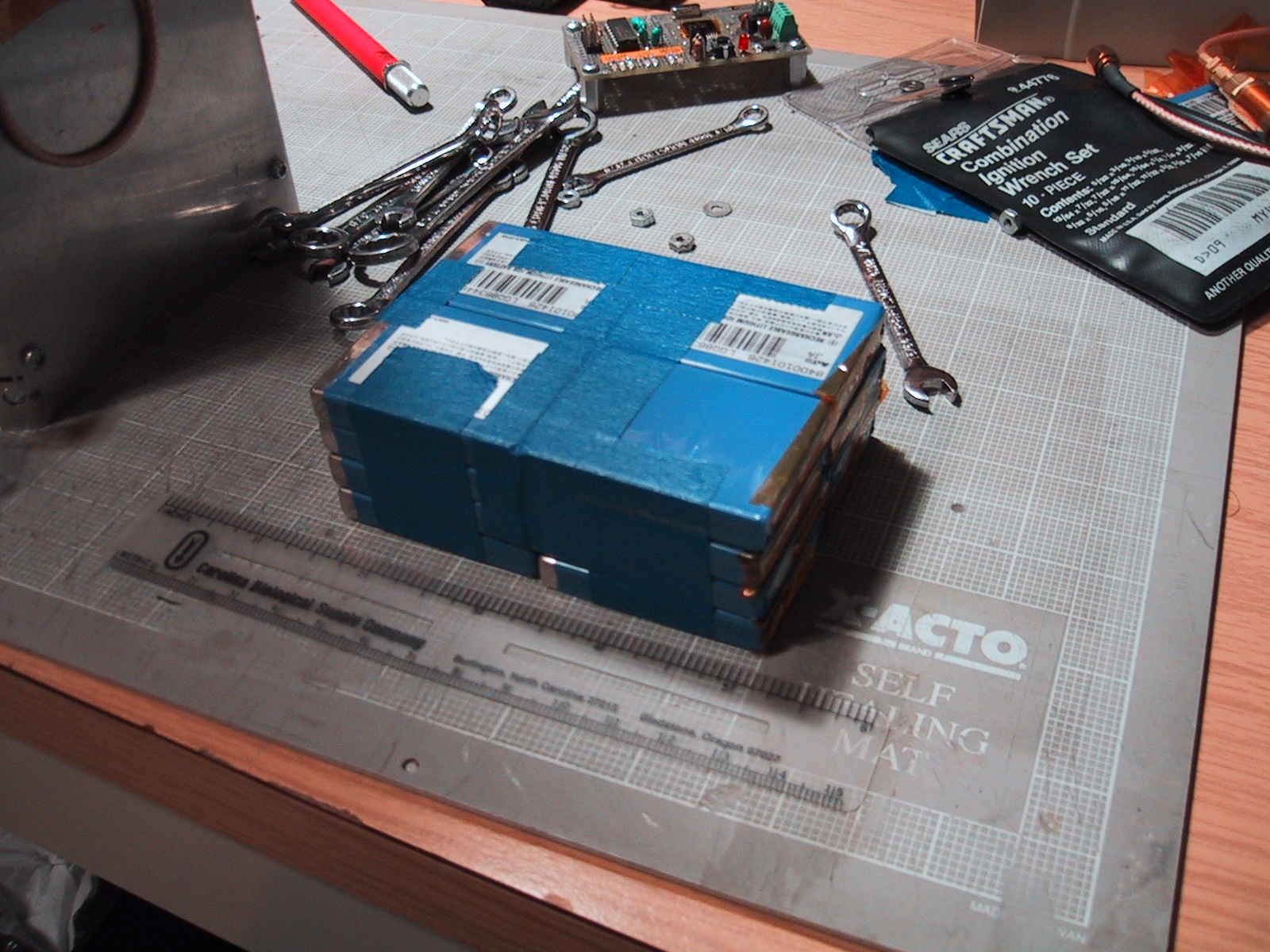
2004/06/15 mockup of the 4S4P battery pack.
So what the hell do you do with 16 steel-encased batteries? Good question.
- Mounting: Sandwich them between the camera "U" bracket on top, and new "U" bracket on the bottom. Fold all edges of the new "U" bracket for added stiffness between the main avionics plates.
- Solder each "parallel cell pack" together first using thick copper straps. Then solder each parallel pack into a carrier PCB and seriesl them there. This allows us to place our coulomb counter and our thermister on the board too, which are wins. Use a piece of plastic with cutouts for the components and solder joints on the bottom of the carrier PCB so they don't get mashed against the new "U" bracket. Maybe even use some double stick foam in there somewhere.
- Although the "U" brackets will hold everything together, we want to be able to swap out the battery packs. So we'll double sticky tape (not foam) the 4 cells together and to the PCB for transport. We'll then put double sticky foam tape between the parallel cells to insulate them, electrically and thermally.
- Use a fuseable link rated at some absurd current, like 10C = 10 * (4 * 1.0 A) = 40 A. That way nothing explodes if we short the batteries together... and if we want a less spectacular show when we short the batteries together, we put an inline fuse in the battery leads until we go for flight.
Here's a sketch of the current ideas:
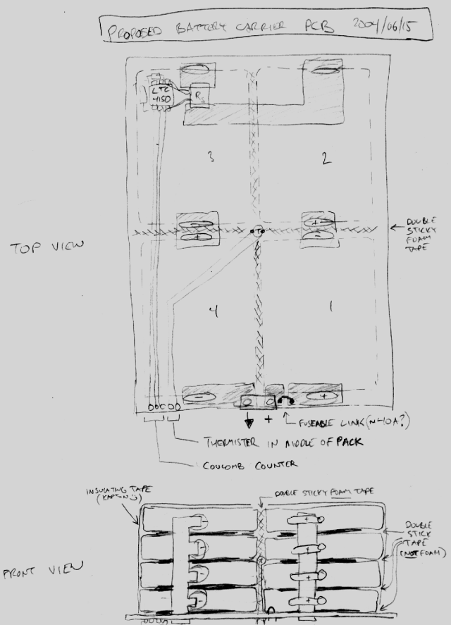
2004/06/15 preliminary pack idea with a rough PCB layout
See the Avionics Power System for more technical information on the coulomb counter and thermister.