Overview
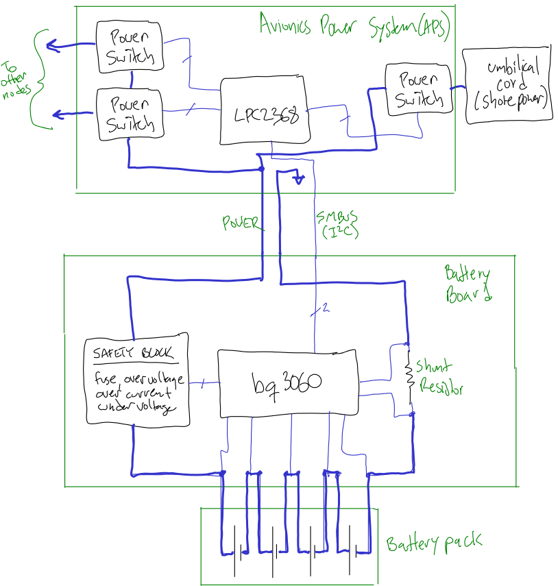
The battery board interfaces the Lithium Ion Polymer battery pack to the avionics power system, which is the power system of the rocket. The battery board does safety functions (overvoltage, undervoltage, overcurrent) and measures the battery's state (voltage, current, state of charge, temperature), and does cell balancing.
Here's a block diagram of how this board fits into the rest of the system:
There's a bit of history behind this board:
- The 2009 Capstone project tried their hands at this board (info here) and got all the way through a schematic and initial layout.
- AV2 flew a very successful battery board with a gas gauge chip: information here and schematic/board here
Requirements
- MUST
- Measure pack voltage which can be (9,16.7,21) V.
- Monitor charge ("coulomb counter") which can be (0, 8, 10) AHr.
- Monitor battery pack temperature (-10 deg C to +80 deg C).
- Fit on front of battery pack (,67 x 24,) mm.
- Be rated for (1,1.5,) C continuous charge and discharge currents (= 12 A for an 8 AHr pack).
- Provide fused short circuit protection of (,2,5) C (= 16 A for an 8 AHr pack), while not false-triggering on turn on capacitive transients of 1,000 uF.
- Provide electronic short circuit protection of 1.5x continuous current rating (= (8,12,)A for an 8 AHr pack), while not false-triggering on turn on capacitive transients of 1,000 uF.
- Be shielded such that metal tools contact will not cause a short circuit in the battery.
- SHOULD
- Separate high current connector from communication connector.
- Monitor the voltage on each cell.
- Do cell balancing.
- Handle deeply discharged batteries.
Other requirements
- According to RocketNames, the battery board components are all numbered in the 1xx regime.
- The battery board will be mounted on
Preliminary Design
Choosing the "maximum current allowed" from the batteries is the most important target to hit here, since this effects the rating and thus expense and avaiablilty of most of the components. We've chosen:
- 15 A fuse (which will allow for current spikes >> 15 A, but should protect the batteries from dead shorts)
- 12 A current limit (1.50 C), enforced by the battery monitor.
- 10 A continuous current (1.25 C) rating for all components.
- 8 A maximum charge rate (1 C) on the batteries.
- < 5A continuous current drain from the batteries (that's 50 - 65 W of continuous power!)
We spent a lot of time looking for a chipset that would do all of this. After a lot of research, we found the TI bq3060 "Smart Battery" chip. It does everything we want, and way, way, way, way more. We should all be very scared of this chip, since it has a RISC core, and comes with flash memory that you can actually upgrade :) So, as long as the complexity of this chip doesn't bite us, it's going to be great. From the data sheet: "The bq3060 provides software 1st level and 2nd level safety protection on overvoltage, undervoltage, overtemperature, and overcharge, as well as hardware-overcurrent in discharge, short circuit in charge and discharge protection." Not too shabby.
Unfortunatately, the evaluation module (EVM) isn't available for this part. But all of the documents, as well as the reference design, are, which is invaluable. We can essentially copy the EVM design, with a few tweaks, and we'll have something usable.
Here's the information on the chip and EVM:
A few notes on the differences between our design and theirs:
- No chemical fuse. They're cool, and nicely fail safe, but we have many other safety circuits which take their place. Both the CHG circuit and the battery charger itself will handle over charging, which is really what we need to be worried about. Overtemp is handled by both the DHG circuit and the APS. Finally, and most importantly, we're already treating this as a dangerous system, so we'll be constantly vigilant for problems. And in the worst case, we'll damage the rocket, as opposed to someone with a laptop on their lap.
- No bq294XX battery protection IC. See discussion above.
Components
F100 main fuse [Littlefuse 0501015.WR, DK F2919CT-ND]
15A fuse in a 1206 package. It's rated at 15 A continuous @ 32 V. It has a nominal R of 0.0025 ohms, and and I^2T rating of 36.100. The data sheets says that it can go for up to 4 hours at its rated 15 A, 10 seconds at 35 A, 1 second at 50 A, and 1 ms at 200 A.
R123 shunt resistor [Vishary WSH2818R0100FEA, DK WSHA-.01CT-ND]
There's no place in the various data sheets that tells you how to pick a resistance for the shunt resistors, but there are clues:
- The bq3060 takes between -.2 to .25 V inputs across the SRP/SRN pins.
- From the data sheet: "using a 5 mΩ to 20 mΩ typ. sense resistor" and from the circuit discussion doc, "For a pack with two parallel cylindrical cells, 10 mΩ is generally ideal."
- The SenseResistor register in the bq3060 contains the value of the sense (shunt) resistor across SRP/SRN. It's set in uOhm, and it can be set from 0 to 65,535 uOhm. The default value is 10,000 uOhm which is 10 mOhm.
- The reference circuit description says "Tc < = 75 ppm in order to minimize current measurement drift with temperature".
- The EVM uses a 0.010 ohm, 1-W, 1%, Tc = 75ppm, 2512 resistor (Vishay WSL-2512-010).
So let's choose 10 mOhm. We could go less, but then we drop voltage gain. We could go higher, but then we power disappation is a problem. 10 mOhm seems like a good engineering comprimise. Now, what power?
- 10 mOhm dissipates 1 W @ 10 A and 2.25 W @ 15 A.
- This means that we need 3W at least in order to not blow up before the fuse in the steady state.
- In a temporary short, we still need to beat the fuse. The 5 second time for the fuse is 40 A, so it ought to handle that.
Here's a comparison of available > 3 W shunt resistors:
| Digi-Key Part Number | P (W) | Tc (ppm/°C) | W | L | Area | W/in^2 | 5 sec over (A) |
|---|---|---|---|---|---|---|---|
| WSRB-.01CT-ND | 3 | 75 | 45 | 27 | 0.1215 | 24.6913580246914 | - |
| WSLI-.01CT-ND | 3 | 50 | 36 | 27 | 0.0972 | 30.8641975308642 | - |
| WSRC-.01CT-ND | 5 | 75 | 45 | 27 | 0.1215 | 41.1522633744856 | - |
| CSSH27280.01FRCT-ND | 4 | 25 | 27 | 28 | 0.0756 | 52.9100529100529 | 44.7213595499958 |
| KRL11C.010CT-ND | 5 | 50 | 43 | 20 | 0.086 | 58.1395348837209 | ?? |
| FCSL90R010FERCT-ND | 4 | 50 | 35 | 18 | 0.063 | 63.4920634920635 | ?? |
| KRL76C.010CT-ND | 3 | 50 | 30 | 15 | 0.045 | 66.6666666666667 | ?? |
| FCSL76R010FERCT-ND | 3 | 50 | 30 | 15 | 0.045 | 66.6666666666667 | ?? |
| WSHA-.01CT-ND | 5 | 75 | 28 | 18 | 0.0504 | 99.2063492063492 | 44.7213595499958 |
| CRA2512-FZ-R010ELFCT-ND | 3 | 75 | 25 | 12 | 0.03 | 100 | 38.7298334620742 |
We choose the WSHA-.01CT-ND (Vishary WSH2818R0100FEA) because it's 5 W but still has a 99 W/in^2 rating, and has 45 A of overrating curent for 5 seconds. The only problem is that the pads are fairly tight together, and there's not a lot of room for getting the Kelvin connections out, but that's OK.
TH100, TH101
- Recommended: Semitec 103AT
Layout
Copper widths
Sunstone uses 0.5 oz/ft^2 Cu on external layers and 1 oz/ft^2 Cu on internal layers. Then they plate the external layers with 0.8 mil Cu, bringing it up another 0.5 oz/ft^2. So we have 1 oz/ft^2 on all layers.
Assuming 2 oz/ft^2 (that is, we can keep the current on two layers at all times), and 300 mm of trace length (connector to ground, B1 to B2, B2 to B3, B3 to B4, and B4 to connector was roughly 270 mm).
When charging, which is our highest current activity, we'll be pumping 8 A through the lines. Most importantly, we don't want that area to heat up very much. So we should burn less than 0.5 W of power during 8A. That's about 0.6% wasted power given a 10V pack, so that seems OK.
Using an on-line calculator, I played around with various trace widths and settled on
- TODO: four layers?
- TODO: see reference schematic?
- Distance between C channels: 3.07" = 78 mm
- Width of the side: 0.6" = 15 mm
- Height of battery pack: 2.34" = 60 mm
TODO
- A red LED & ALARM buzzer tied to ground on the FUSE output, maybe? Or as separate safety circuit somehow?