Cylindrical Patch Antenna Design for LV2
Back to the Communications Team Homepage.
We're designing 3 cylindrical patch antennas (CPAs) for LV2.
v3 CPA Design
Please see the CPA version 3 design page for the latest designs.
Here's the construction notes: CpaConstructionv3
v2 CPA Design
So far it's been going moderately well. We fabricated cylindrical antennas using foamed polyethylene dielectric. However the frequencies were not exactly as predicted. We want better than 1% accuracy in frequency (10MHz out of 1GHz), but we are getter closer to -5% accuracy.
To better understand the problem we fabricated and trimmed flat patch antennas similar to the cylindrical models.
The major source of error has been determined to be improper calculation of the resonant patch length. This has been corrected, but inverting the current antenna model to derive the dielectric constant of the foamed polyethylene gives inconsistent results.
The cylindrical antennas give a constant dielectric constant vs frequency, while the flat antennas seem to indicate a dielectric constant that rises with frequency. So far this difference is unexplained. See the following graph.
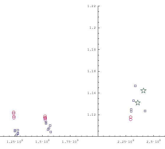
In the previous graph the vertical axis plots the relative dielectric constant of the polyethylene foam, while the horizontal axis is the resonant frequency of the antenna when the measurement was made, in Hz. The red circles are measurements from the cylindrical patch antennas while the blue boxes are measurements from the flat-patch test-antennas.
Ah Ha! Finally we found a decent measurement of the permittivity of polyethylene. Impulse Propagation Measurements of the Dielectric Properties of Several Polymer Resins: Measurement Note 55 by Bigelow and Farr of Farr Research Inc. Nov. 1999.
In the reference, figure 8 (p.12) gives the real part of epsilon_r for UHMW polyethylene from 300 MHz to past 10 GHz. The relevant information for our purposes is that epsilon_r = 2.28918 @ 1 GHz and 2.28903 @ 2.5 GHz, this is a change of only about -65 ppm, almost constant for our purposes.
The standard caveats apply. Our antenna dielectric material is not well characterized, and not UHMW, but UHMW is so flat that it seems likely our material is fairly flat as well.
Antenna Test Data (Last update 2004.2.10)
This represents all our test data so far.
Note that "-" indicates the data has not been taken and probably won't be. Blank spaces are more ambiguous.
Build Order
| 1 | Cy802 | Cylindrical, built in Black Rock |
| 2 | CyGPS | Cylindrical, built in Black Rock |
| 3 | CyATV | Cylindrical, built in Black Rock |
| 4 | F802 | Flat, built in Portland |
| 5 | FGPS | Flat, built in Portland |
| 6 | FATV | Flat, built in Portland |
| 7 | CY802.2 | Cylindrical, 2nd round test, 2004.2.6 |
| 8 | CYGPS.2 | Cylindrical, 2nd round test, 2004.2.6 |
Antenna Dielectric Thickness
| Antenna | Thickness | comment |
|---|---|---|
| Name | (mm) | |
| Cy802 | 1.78 | tab |
| CyGPS | 1.65 | tab |
| CyATV | 1.7 | tab |
| F802 | 1.6 | Andrew |
| FGPS | 1.52 | Andrew |
| FATV | 1.57 | Andrew+tab |
| Cy802.2 | 1.42 | tab |
| CyGPS.2 | 1.42 | Jared |
Frequency Data Table
| Antenna | Length | Freq. | SWR | BW | comment |
|---|---|---|---|---|---|
| Name | (mm) | (GHz) | (MHz) | ||
| CyATV | 109.65 | 1.240 | 1.423 | - | 20031006, Glenn |
| Cy802 | 57.81 | 2.293 | 1.07 | 68 | 20031010, Glenn+ADG |
| CyGPS | 88.88 | 1.524 | 1.07 | 37 | 20031010, Glenn+ADG |
| CyATV | 109.65 | 1.242 | 1.36 | - | 20031010, Glenn+ADG |
| F802 | 57.81 | 2.298 | 1.1 | - | 20031020, GAT+Tom |
| F802 | 57.8 | 2.297 | 1.1 | - | 20031020, GAT+Tom, -0mm, Proves non-difference of removed fiberglass |
| F802 | 57.03 | 2.319 | 1.1 | 52 | 20031020, GAT+Tom, -1mm |
| F802 | 56.28 | 2.336 | 1.21 | - | 20031020, GAT+Tom, -2mm |
| F802 | 54.7 | 2.422 | 1.284 | 54 | 20031020, GAT+Tom, -3.7mm |
| FGPS | 88.88 | 1.53 | 1.11 | - | 20031110, GAT |
| FGPS | 88.8 | 1.532 | 1.11 | - | 20031110, GAT, -0mm |
| FGPS | 88.0 | 1.549 | 1.07 | - | 20031110, GAT, -0.88mm |
| FGPS | 87.43 | 1.558 | 1.05 | - | 20031110, GAT, -1.38mm |
| FGPS | 86.7 | 1.569 | 1.05 | 24 | 20031110, GAT, -2.36mm |
| FGPS | 86.7 | 1.573 | 1.06 | - | 20031110, GAT, -2.46mm, burnished-inconsistent |
| FATV | 109.65 | 1.251 | 1.16 | 15 | 20031110, GAT |
| FATV | 109.6 | 1.252 | 1.15 | - | 20031110, GAT, -0mm |
| FATV | 108.6 | 1.265 | 1.3 | - | 20031110, GAT, -1mm |
| FATV | 107.35 | 1.2785 | 1.35 | 12 | 20031110, GAT, -2.15mm |
| FATV | 107.35 | 1.2787 | 1.34 | 13 | 20031110, GAT, -2.15mm, calibration check after error |
| FGPS | 56.25 | 2.357 | 2.21 | - | 20031110, GAT, -32.62mm, change GPS to WiFi |
| FGPS | 54.75 | 2.408 | 2.75 | - | 20031110, GAT, -34.18mm, a little fat on one end |
| FGPS | 44.25 | 2.879 | 1.11 | - | 20031110, GAT, -44.7mm, change GPS to 3GHz, a little fat on one end again |
| FATV | 107.35 | 1.277 | 1.3 | 14 | 20031122, GAT+ |
| CyATV | 109.65 | 1.242 | 1.48 | - | 20031122, GAT+ |
| CyGPS | 88.88 | 1.523 | 1.16 | 89 | 20031122, GAT+, anomalous bandwidth |
| F802 | 54.7 | 2.422 | 1.3 | 53 | 20031122, GAT+ |
| Cy802.2 | 57.81 | 2.2979 | 53 | 20040210, Glenn+Jared | |
| CyGPS.2 | 88.88 | 1.5211 | 1.09 | 27 | 20040210, Glenn+Jared |
Previous Work
The preliminary design is based on guidance from Antenna Engineering Handbook, Microstrip Patch Antennas. Our design notes are attached as sheets 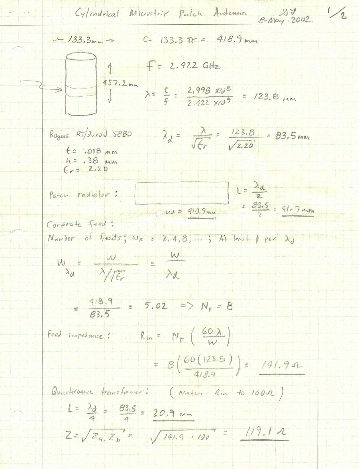 and
and 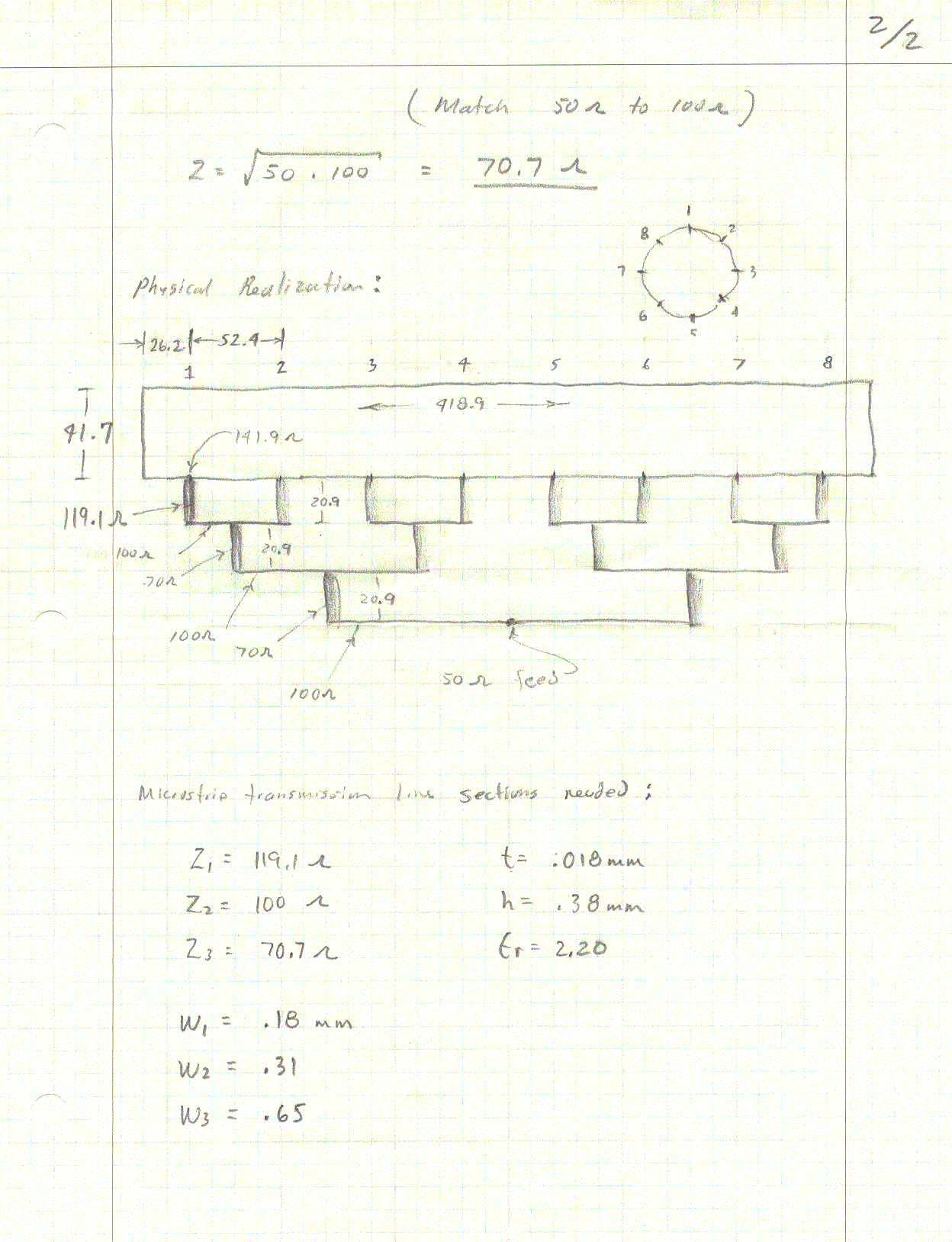 below. These ideas have been captured in a spreadsheet.
We hope to be able to simulate our antenna designs in order to transition from a theoretical design, to actual real-world performance with a minimum of cut-and-try.
There are two metrics we are concerned with regarding antenna performance. We want the impedance to be as close to purely-resistive @ 50ohms as possible, and return energy to be infinitesimal. These can be found by understanding the scattering parameter S11. Simulation programs can provide this information for a specified design. It is through our preliminary design as a starting point, and through stepwise refinement using simulation, that we can obtain a (hopefully close to) successful one-off design.
After preliminary design, and optimization using simulation, we can be confident of a design worthy of fabrication.
After the fabrication process, which is mostly driven by material dimensions, a test can be performed. A bench test can show SWR, or other S11 parameters through use of a microwave network analyzer.
Design Software
ANSOFT was kind enough to give us a copy of Clementine, a cylindrical patch antenna simulator (?Contacts). They also gave us a copy of ?HFSS.
cpa calculator 3.xls: an Excel spread sheet (but should work fine under OpenOffice/gnumeric) which calculates everything we need to know about cylindrical patch antennas. All equations are based off of the Antenna Engineering Handbook, third edition, Ed. Richard Johnson.
We also have some older ?software which we can use to double check our calculator.
References
Antenna Engineering Handbook
Tektronix Analog Design System (ADS) User Manual T0-6360-00
ads2.pdf (3.1M)
Contains several microstrip design equations in the chapter on application models.
Guillermo Gonzalez, Microwave Transistor Amplifiers, 2nd ed. 1997
Sullins, Ty, Design of circularly polarized omnidirectional microstrip sounding rocket antennas for telemetry and GPS applications. Diss. U of Alaska, Fairbanks, 2001.
Dielectric Characterization of Material Lab Notes
http://www.upv.es/gcm/lab/cdm.htm
Michael D. Janezic, Jeffrey A. Jargon, Complex Permittivity Determination from Propagation Constant Measurements
IEEE Microwave and Guided Wave Letters, v.9 n.2 Feb.1999
http://www.boulder.nist.gov/div813/rfelec/device/Publications/RelatedPublications/MGWL99_Permittivity.pdf
Robert A. Sainati, CAD of Microstrip Antennas for Wireless Applications, 1996, Artech House Inc.
ARRL Satellite Experimenters Handbook has a list of ?RadomeMaterials
Interesting links:
- Four element cylindrical patch antenna for a rotating axle. Interesting points: 1) a dielectric which is too thick excites side lobes. 2) adding a "radome" (a rubber sealant) brought down the resonant frequency 1-2% so you can design that in to the original antenna.
- Antenna Research Associates makes a CPA:
- And of course, our commercial favorite:
Attachments: