Glenn and Andrew got together and made flat patches.
Here's the rough order of steps:
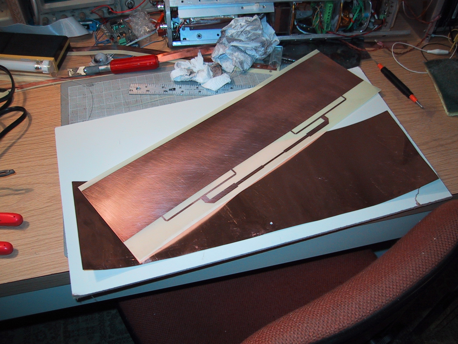
- Cut out the patch (pre-etched 5/1000 inch thick FR-4)
- Cut out the ground plane, using the patch as a guide (the ground plane is soft copper sheeting 5/1000 inch thick)
- Align the PCB and ground plane, and poke through the PCB feed hole with something sharp (e.g., oscilloscope probe) to make an indent.
- Drill or use an exacto to cut out a hole just big enough for the center insulation.
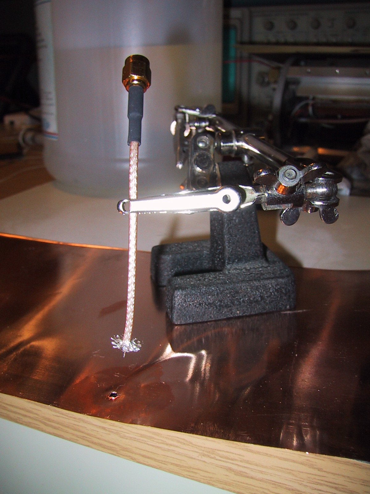
- Cut back the coax jacket and splay out the braid. Cut and strip the center conductor (although you might have to strip it again later).
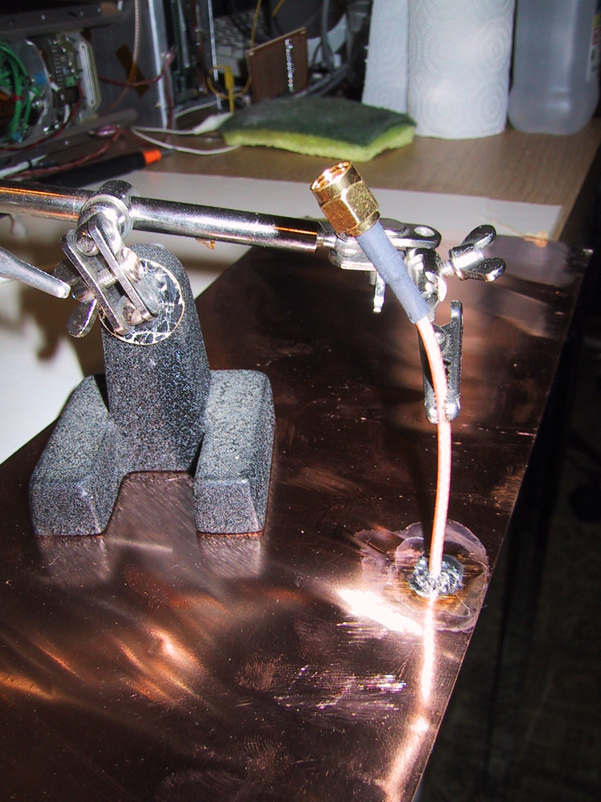
- Clean up the copper ground plane with nonresidue flux, and solder it on with a big soldering gun. The insulation and center conductor are now sitting poking out through the copper ground plane.
- Apply the foam tape. Don't forget to make a hole in the foam tape for the insulation and center conductor.
- DO NOT REMOVE THE PLASTIC RELEASE TAPE ON TOP OF THE FOAM TAPE.
- Slit the plastic tape starting right at the center conductor in a line perpendicular to the long axis of the antenna.
- Put the PCB on the center conductor and very carefully hold it down near that point.
- If the center conductor's insulation is too long, it will push up on the feedpoint, take off the PCB and trim it down.
- You might want to solder it on at this point.
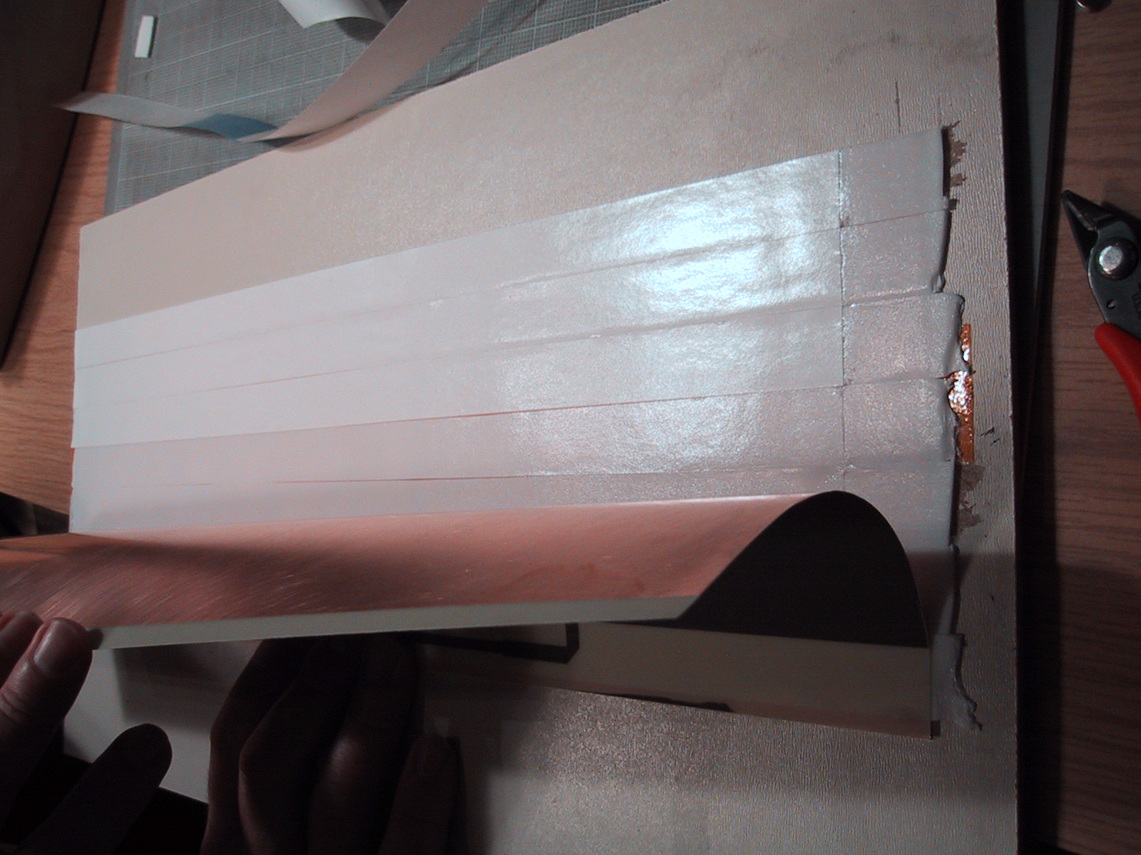
- Then, bend the PCB and begin removing the plastic tape. START AT THE BOTTOM OF THE ANTENNA, AND WORK YOUR WAY UP, SMOOTHING OUT THE PCB AS YOU GO UP.
- Voila, you've got a flat CPA.