Coordinate System Conventions
( See also our mathematical notation page)
Body Reference Frame Naming Conventions
Fig. 1 shows the coordinate convention used for our rocket.
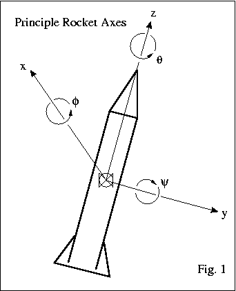
We tried, but nobody would use anything but theta(θ) to indicate roll, so we went with that. The <xyz> axes form a right handed coordinate system where roll is measured on the z axis parallel to the body axis. We arbitrarily assign the x axis to be pitch with angle phi(φ), and the y axis to be yaw with angle psi(ψ). The intention is to assign the axis of the horizon camera as the x axis, though we don't expect perfect alignment so probably whichever IMU axis is nearly parallel to the horizon camera will be the "real" x axis.
A somewhat old document referring to this is available here: Body Reference Frame.pdf
The only modification to this document (so far) is that we've switched the names of the angular variables, as indicated before, the system is now:
- phi(φ) = pitch (x)
- psi(ψ) = yaw (y)
- theta(θ) = roll (z)
Ground Reference Frame
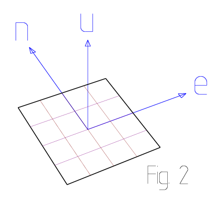
Since for now we're doing only relatively low altitude sounding rocket flights, we like to define our local coordinate system assuming a flat Earth. That is, we define a rectangular coordinate system centered on our launch site with "up" defined by the gravity-plumb line. To keep this system easy to use we align the (x) axis with true East and the (y) axis to true North. The resulting East-North-Up <enu> system is a right handed rectangular coordinate system as shown in the next figure.
For more information including the formula for transforming from ECEF-g (Earth Centered Earth Fixed Geodetic) to <enu> please see the attached document: Latitude to LocalTangent.pdf
Position Reference Frame Summary
| Frame | Symbol | coordinates | Notes |
|---|---|---|---|
| Sensor | s | <f, u, t> | Unique to each sensor |
| Platform | p | <x, y, z> | IMU reference frame |
| Body | b | <x, y, z> | Same frame as mechanical design |
| Tangent | t | <e, n, u> | INS output frame |
| ECEF-r | r | <x, y, z> | GPS Cartesian frame |
| Geodetic | g | <λ, φ, h> | GPS lat., lon., height |
Each position reference frame defines a right-handed coordinate system.
A sensor frame is defined for every direction sensitive axis, this includes each accelerometer, gyro, and magnetometer axis. The sensor frames allow for formal accounting of sensor misalignment. The sensor axis names are <(f)orward, (u)p, (t)ransverse>
The platform frame is the natural output frame of the IMU. It defines three orthogonal <xyz> axes with a fixed orientation relative to the body frame. The platform frame is transformed to the navigation frame when aggregating navigation information for vehicle control.
The body frame is the tied to the physical airframe. It is the natural frame for control surface and vehicle attitude control. The body to platform transformation is important for calculating control outputs during active guidance.
The tangent plane is the locally aligned Cartesian coordinate frame. In the tangent frame ground level is at (u=0). A closely related frame defines height as geodetic height relative to the WGS84 ellipsoid, so some caution should be used in keeping the zero-altitude reference consistent. The tangent axis names are <(e)ast, (n)orth, (u)p>
The ECEF-r coordinates are Earth-Centered, Earth-Fixed, rectangular coordinates. Earth-Centered meaning the origin is at the center of the Earth, Earth-Fixed meaning the x axis passes through the equator at the prime meridian (longitude = latitude = zero). ECEF-r rotates with the Earth and is therefore not an inertial frame. ECEF-r coordinates are available from most off the shelf GPS units.
Geodetic coordinates (also known as ECEF-g) are the primary coordinates of the GPS. They are based on the WGS84 ellipsoid. In particular Geodetic height is measured relative to the ellipsoid. (Note that some references reverse the symbols for latitude(λ) and longitude(φ). We prefer the definition given here.)
The navigation frame is the frame used for path planning and other tracking and control purposes. No specific navigation frame is defined here. The frame appropriate for navigation is application dependent, and may even vary within a single application. When defined, the navigation frame is symbolized by the letter (n).
Aerodynamic parameters in body frame coordinates
Lift and drag are not typically aligned with the body frame axes. The next figure indicates the relationship and suggests some conventions for labeling lift, drag, and some other body forces.
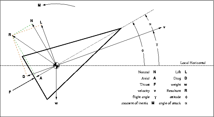
Lift and Drag in body coordinates