In attendace: Andrew, Glenn, Timr, Jared and Dave.
Special thanks to: NW EMC, Holly, and Rod for making this possible.
Summary: We took the LV2.1 airframe, along with the cylindrical patch antennas (CPAs) on the avionics module to NW EMC in Hillsboro to do propogation measurements. We did three polar plots of each cylindrical patch antenna at it's natural frequency (which was not the design frequency): one azimuth and two elevations (at 90 degrees to each other). We then took azimuth readings on a 2.422 and 1.253 GHz reference dipole, and finally took azimuth and a single elevation reading for the 1.5 GHz slot antenna.
Pre-lab:
- Build 2.4, 1.5, 1.2 GHz reference dipoles - only 2.4 and 1.2 built
- Rebuild 2.4, 1.5 and 1.2 GHz baluns for slot antennas - only 2.4 and 1.5 built
Things to bring:
- CPAs, LV2.1 airframe, Kapton tape, xacto knife, blades, scissors, foam tape, calipers, etc - Andrew
- Reference dipoles, patch cables, etc - Glenn
- Patch cables, etc - Timr
Would have been useful:
- Non-metalic stand for LV2.1
- Our own packing tape (we used two spools of NW EMC's)
- Some kind of ability to quickly switch antennas from one feed connector
Test Plan:
Test antennas.
- Measure the propagation of the v2 WiFi cylindrical patch antennas on the airframe:
- At 2.422 GHz, 2.422 GHz + 15 MHz, 2.422 GHz - 15 MHz
- Azimouth
- Elevation at 0,90 degrees
- Measure the GPS CPA as possible
- Measure the ATV CPA as possible
Measure and possibly tune the 2.4, 1.5, and 1.3 GHz reference dipoles at the freq, freq - BW, freq + BW.
- Measure 3 slots
Getting there:
We're meeting there at 5:00pm SHARP. Do NOT be late! We've got 20 hours of testing to do in 4 hours ;)
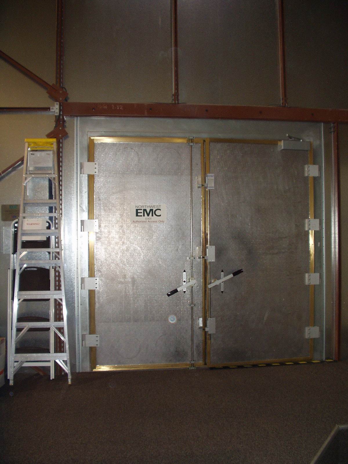
Northwest EMC, Inc. 22975 NW Evergreen Parkway, Suite 400 Hillsboro, OR 97124 (503) 844-4066
And you can get maps at their web site: http://www.nwemc.com/hillsboro.html
Testing Notes
Given the time constraints, we decided to do only three tests per antenna and throw out the idea of doing off-natural frequency tests (for bandwidth).
Holly and Rod calibrated the chamber for each of the cylindrical patch antenna frequencies: 2.29328, 1.52438 and 1.24259 GHz (as measured previously).
We then had to make a decision: how to set the vertical height of the receive antenna. Holly and Rod set the height during chamber calibration to maximize the signal strength of the calibration horn antenna. We really wanted the geometric scan to be correct - i.e., we wanted the receive antenna to be on axis to the rocket so we could really get the geometric cut through the propagation space we wanted. This apparently throws off the absolute measurements of the system, and thus the absolute calculations are called "pseudo-absolute" because of this lack of maximizing the signal.
"Configuration" Notes
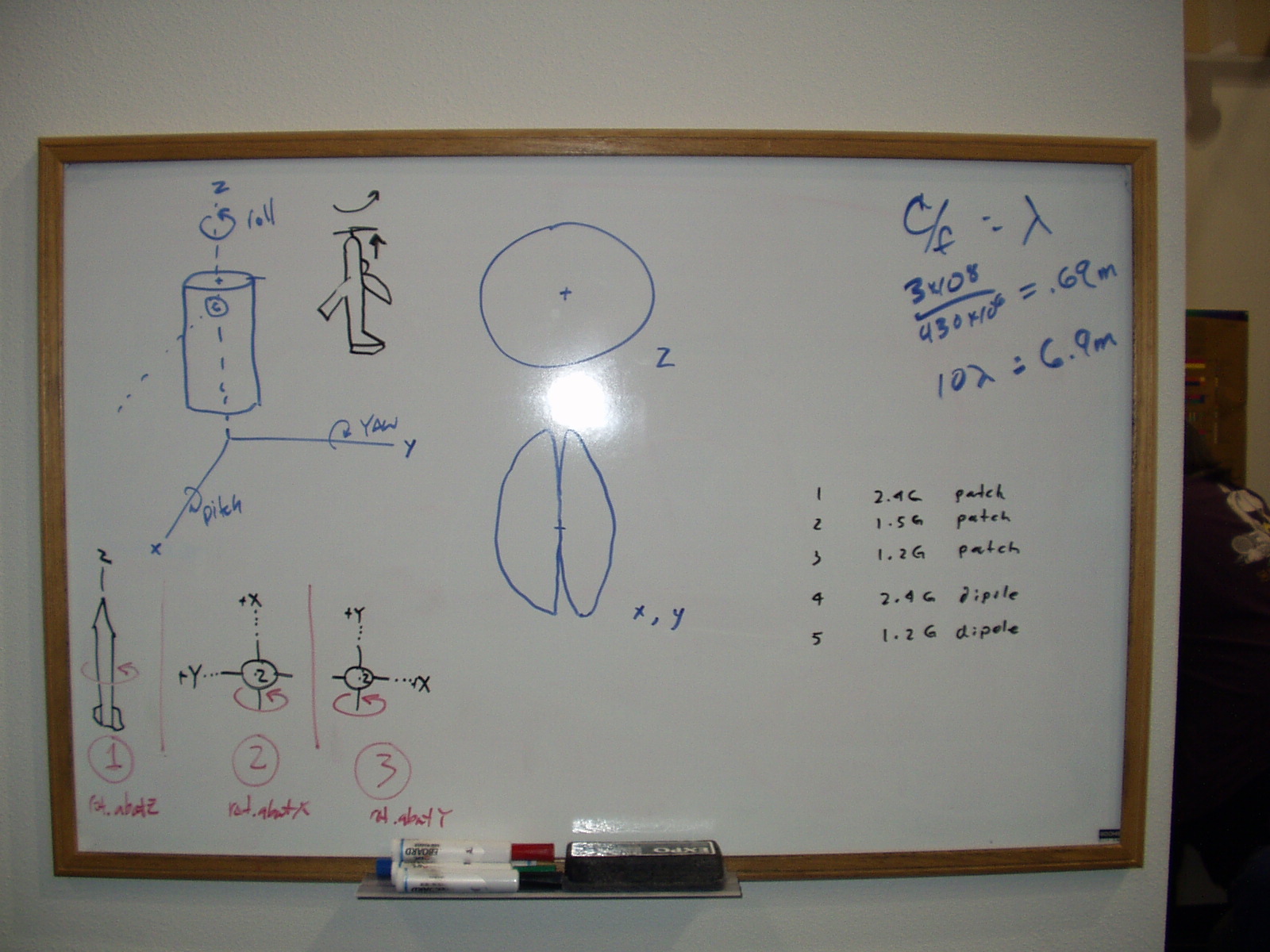
To understand what test we did, we had to define the axes and test configurations (positions) of the antennas (and thus rocket). We used the inertial definitions of the rocket to be consistent: while on the launch tower, the +Z axis is straight up, the +X axis is straight out from the rocket away from the launch rail, and +Y follows the right hand rule (Z is the thumb, X is the index and Y is the middle finger).
To map this to the avionics module, this means the positive X axis starts at the center of the cylinder and goes out through the same vertical plane that cuts through the center of the camera lens. The Y axis is 90 degrees to the right looking down the tube (again, the right hand rule where Z is the thumb, X is the index and Y is the middle finger).
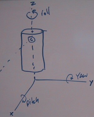
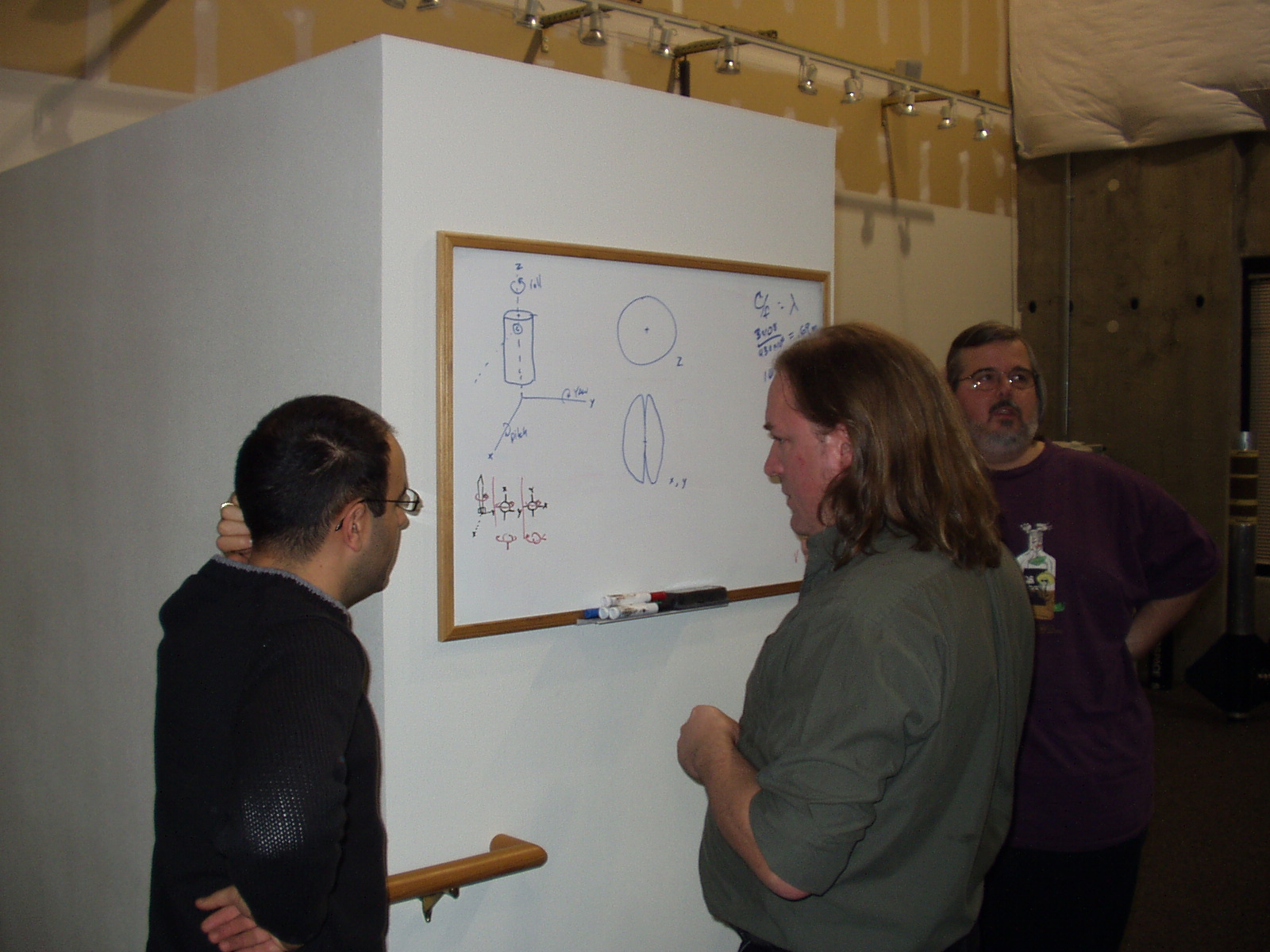
X,Y and Z axes defined for the Avionics Module. The circle with a "c" in it is the ATV camera lens.
Given these definitions, we then defined the test configurations as:
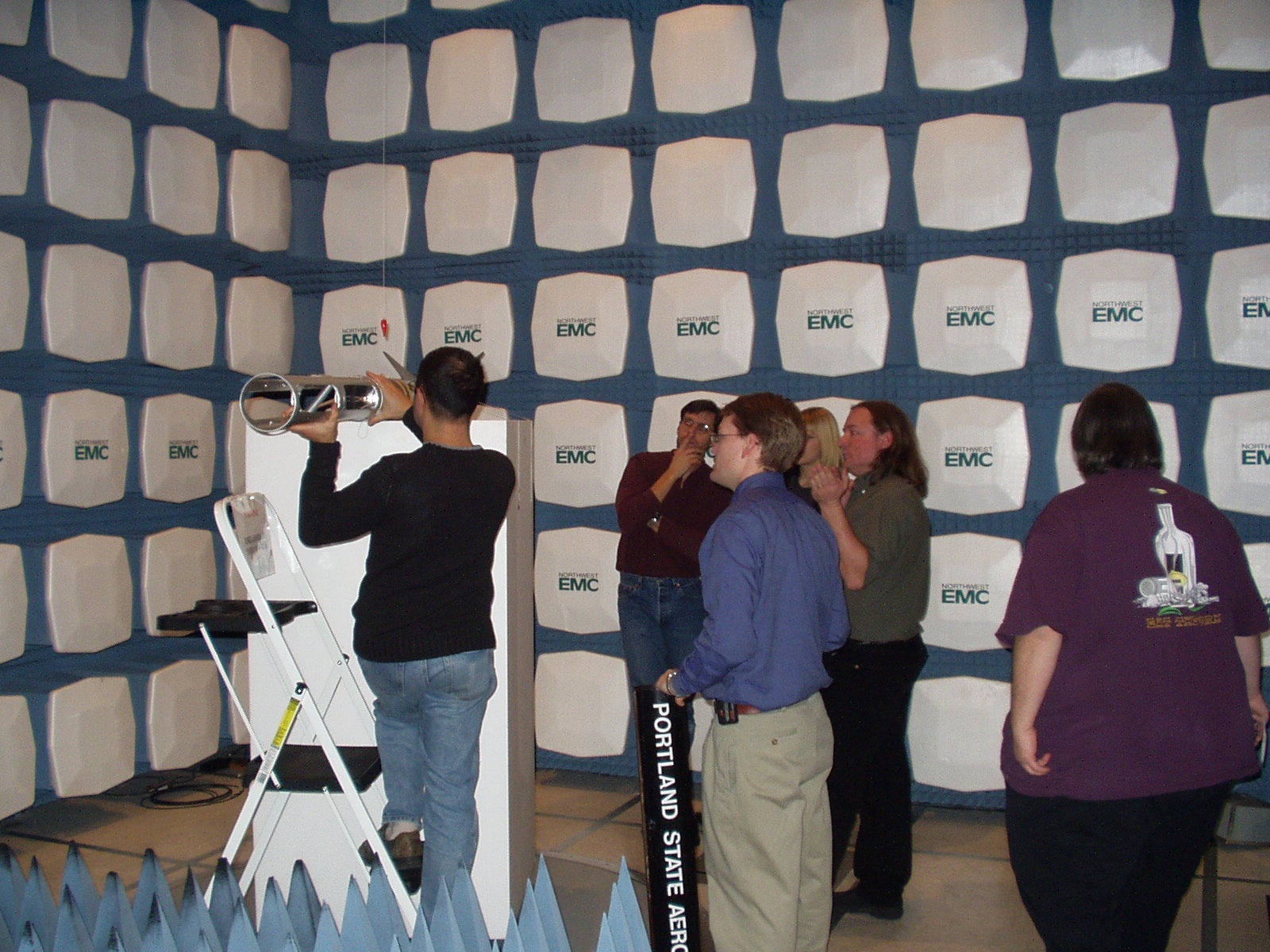
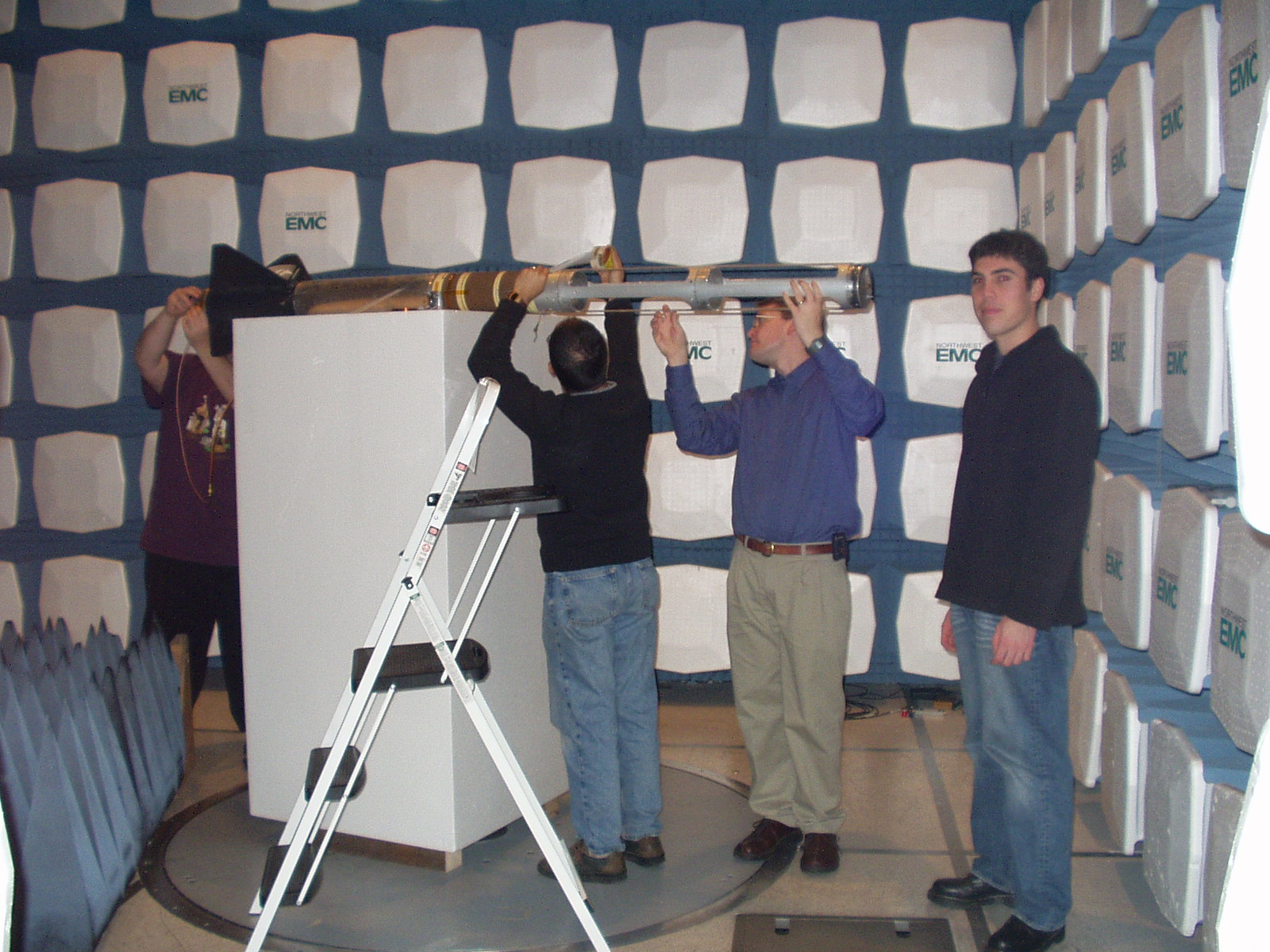
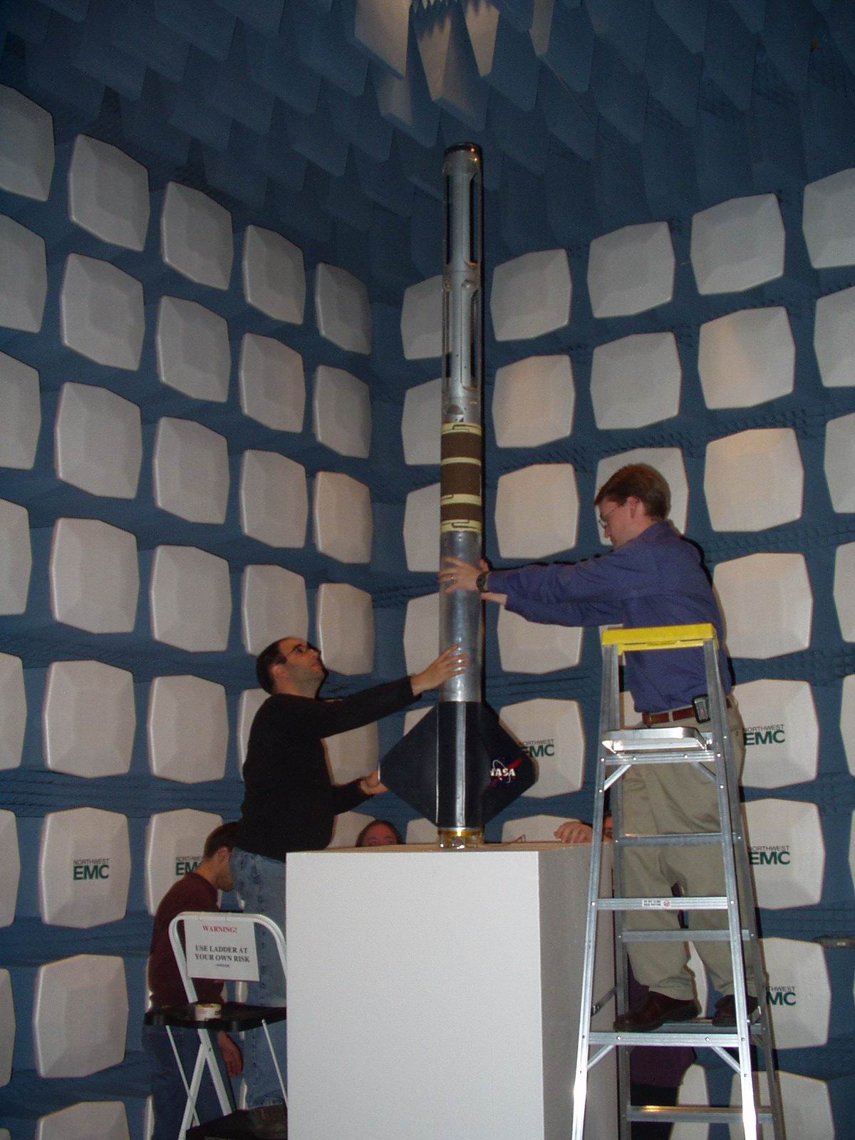
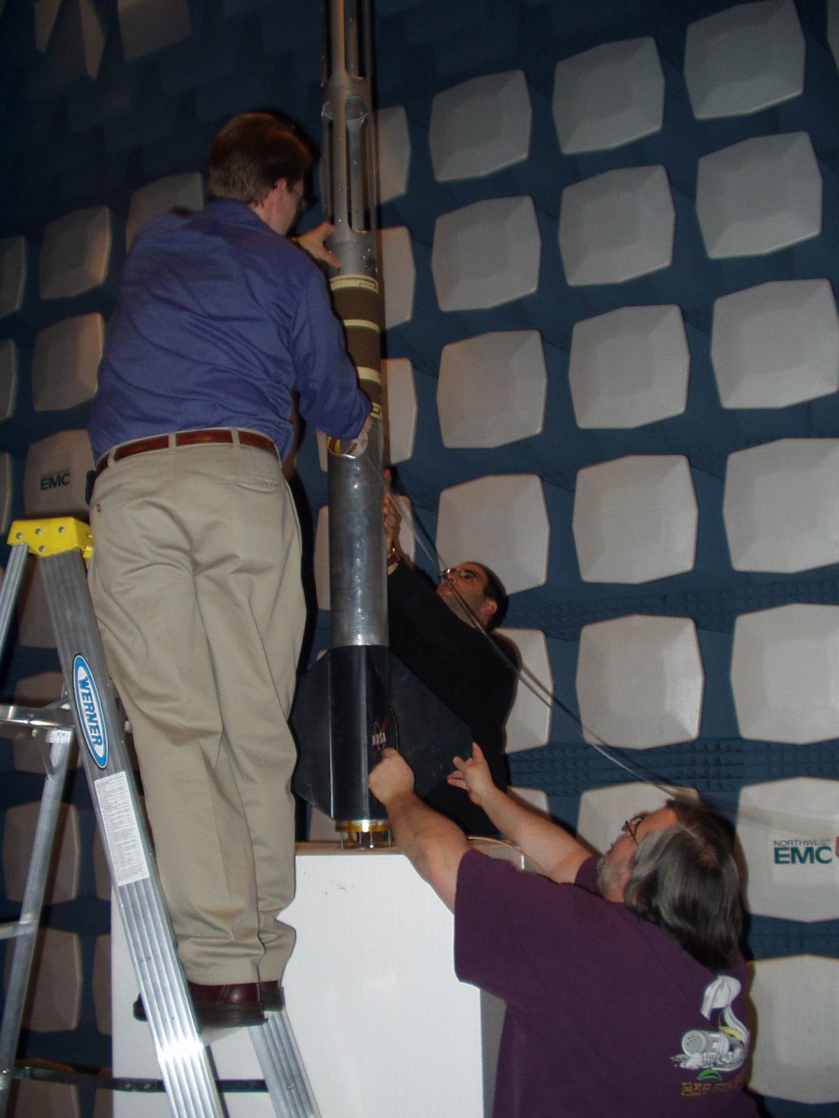
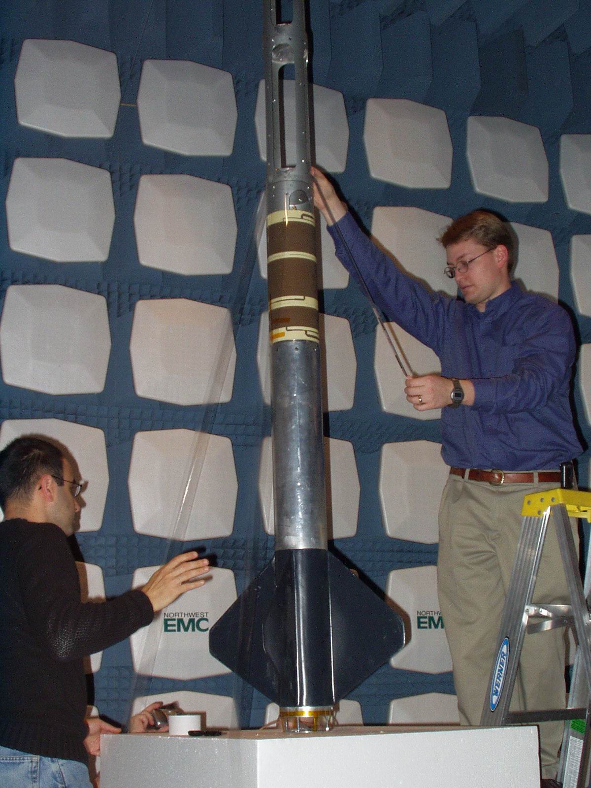
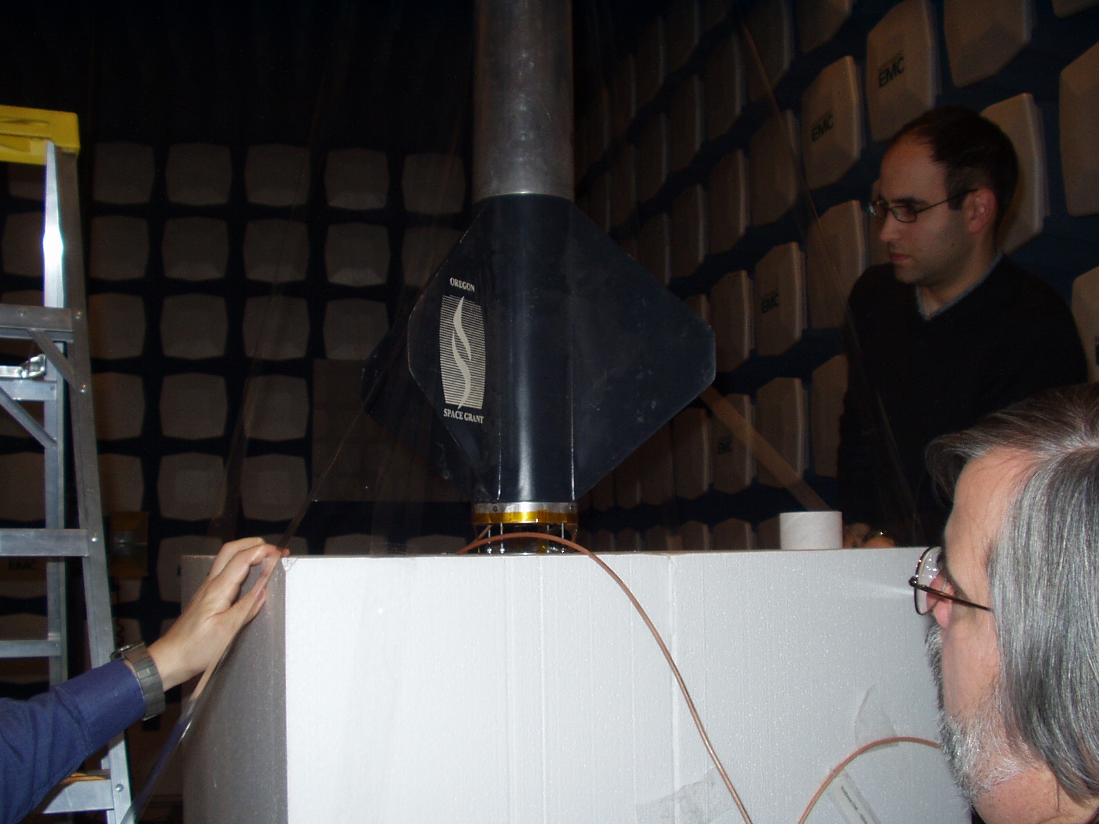
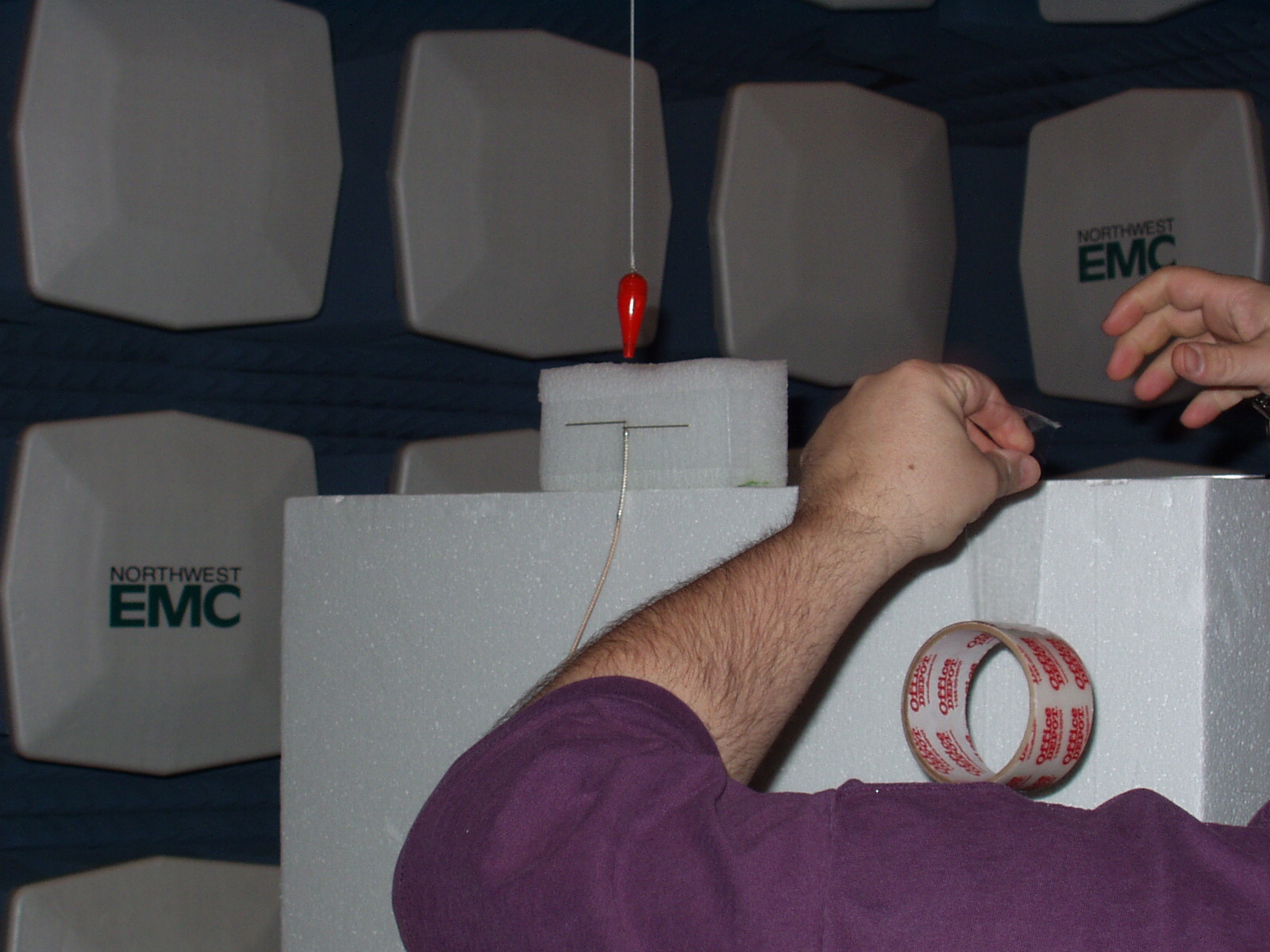
Configuration 1: Azimuth, rotation around the Z axis ("roll"): We put the rocket on standing vertially on top of a ~1.5 m block of styrofoam, using packing tape to secure the base and payload module in the middle.
Configuration 2: Elevation 1, rotation around the X axis ("pitch"): We laid the rocket down on its side with the X axis pointing straight up.
Configuration 3: Elevation 2, rotation around the Y axis ("yaw"): We laid the rocket down on its side with the Y axis pointing straight up.. similar to Configuration 2 but at 90 degrees.
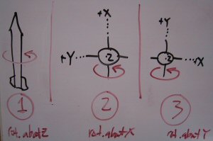
Sketches of Configurations and LV2.1 Axes. Note Configuration 1 starts with the X axis pointing towards the receive antenna.

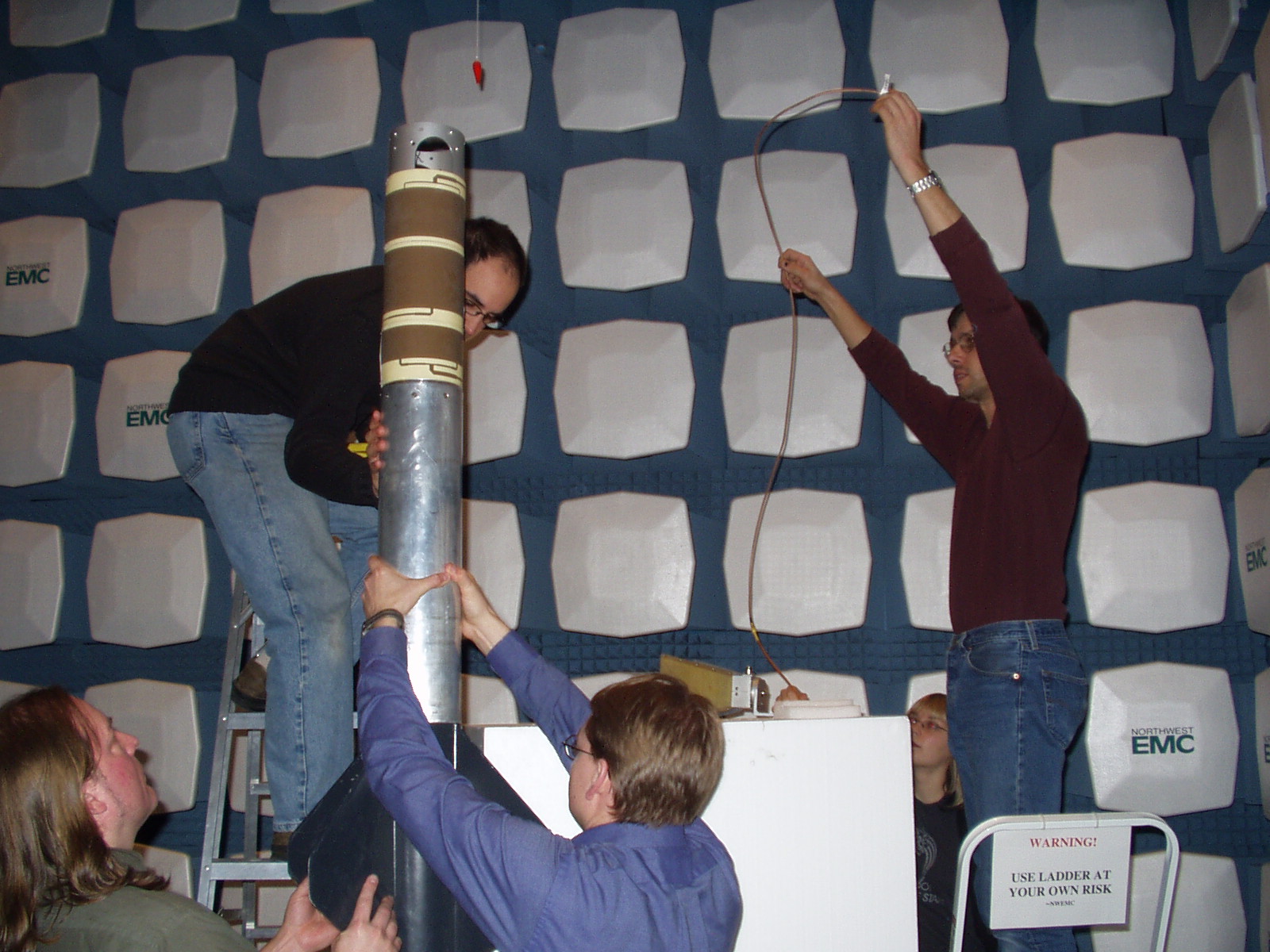
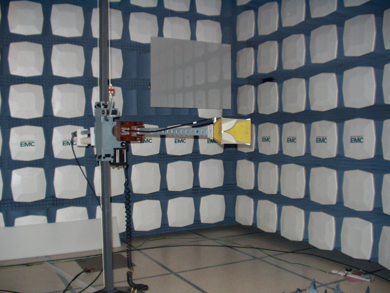
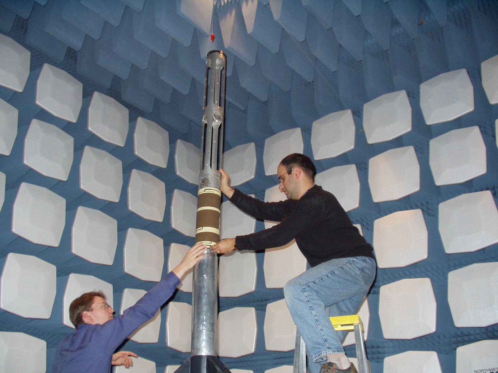
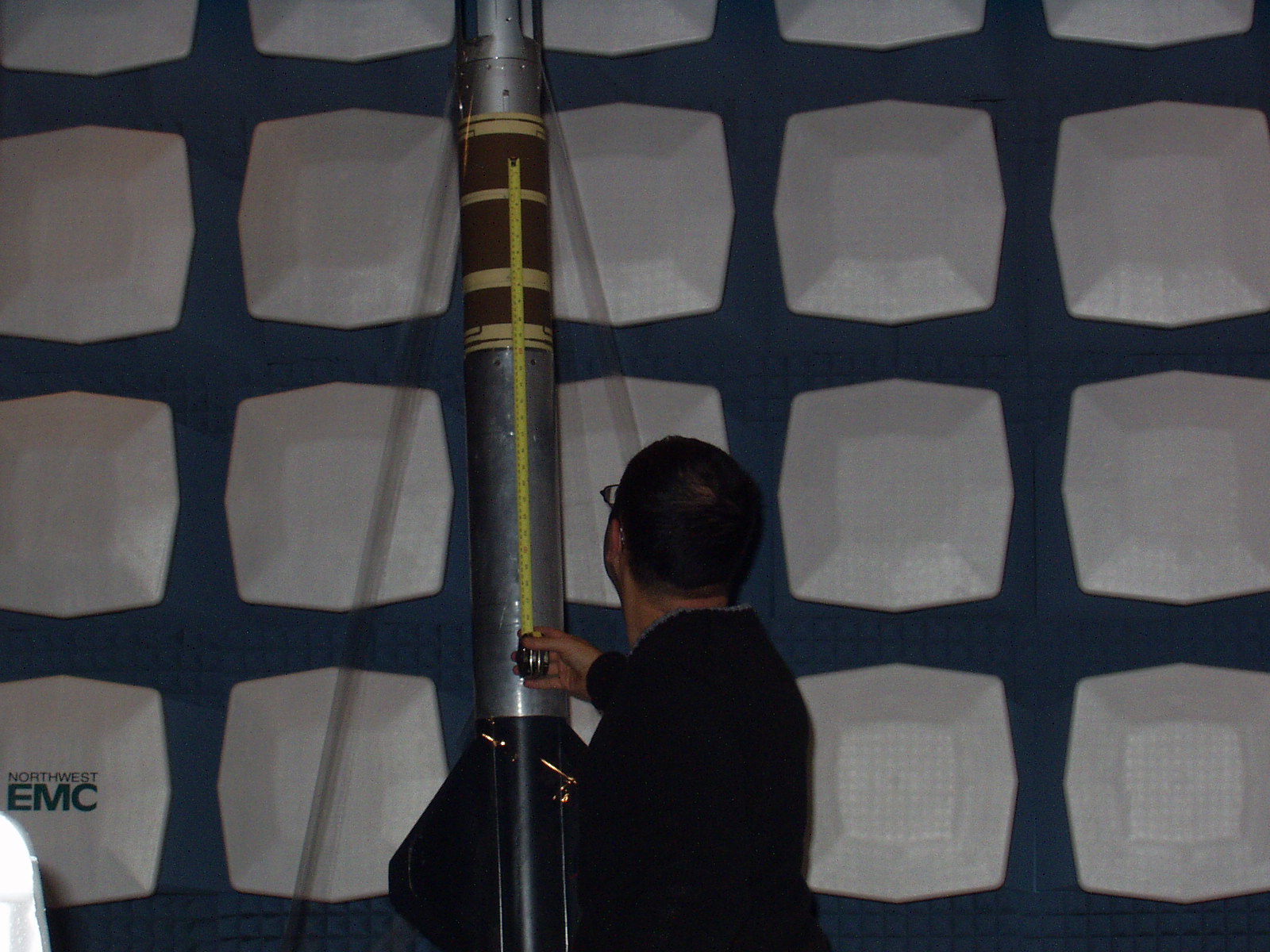
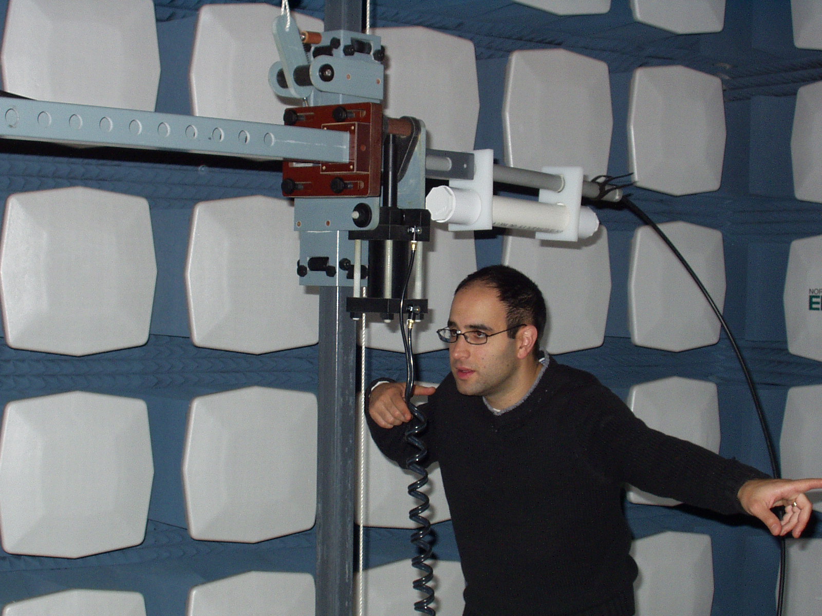
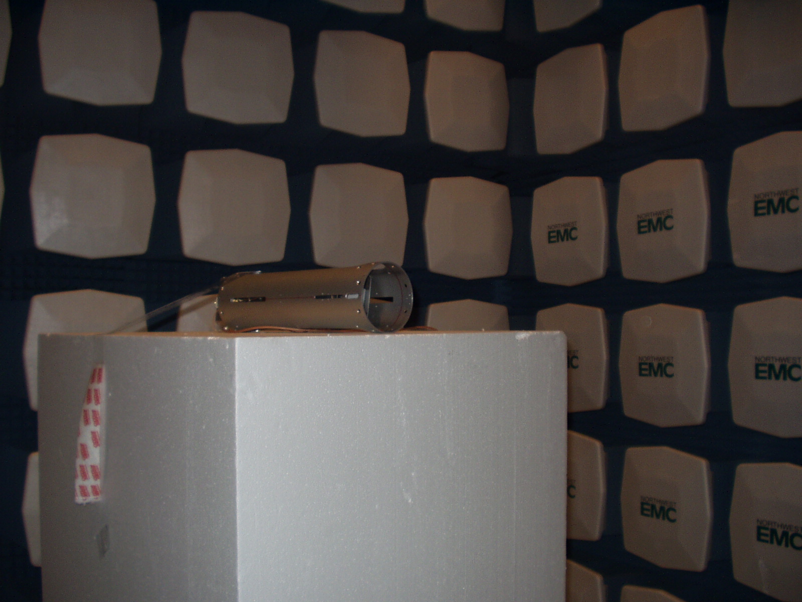
Photo of LV2.1 in Configuration 1 from right in front of the receive antenna.
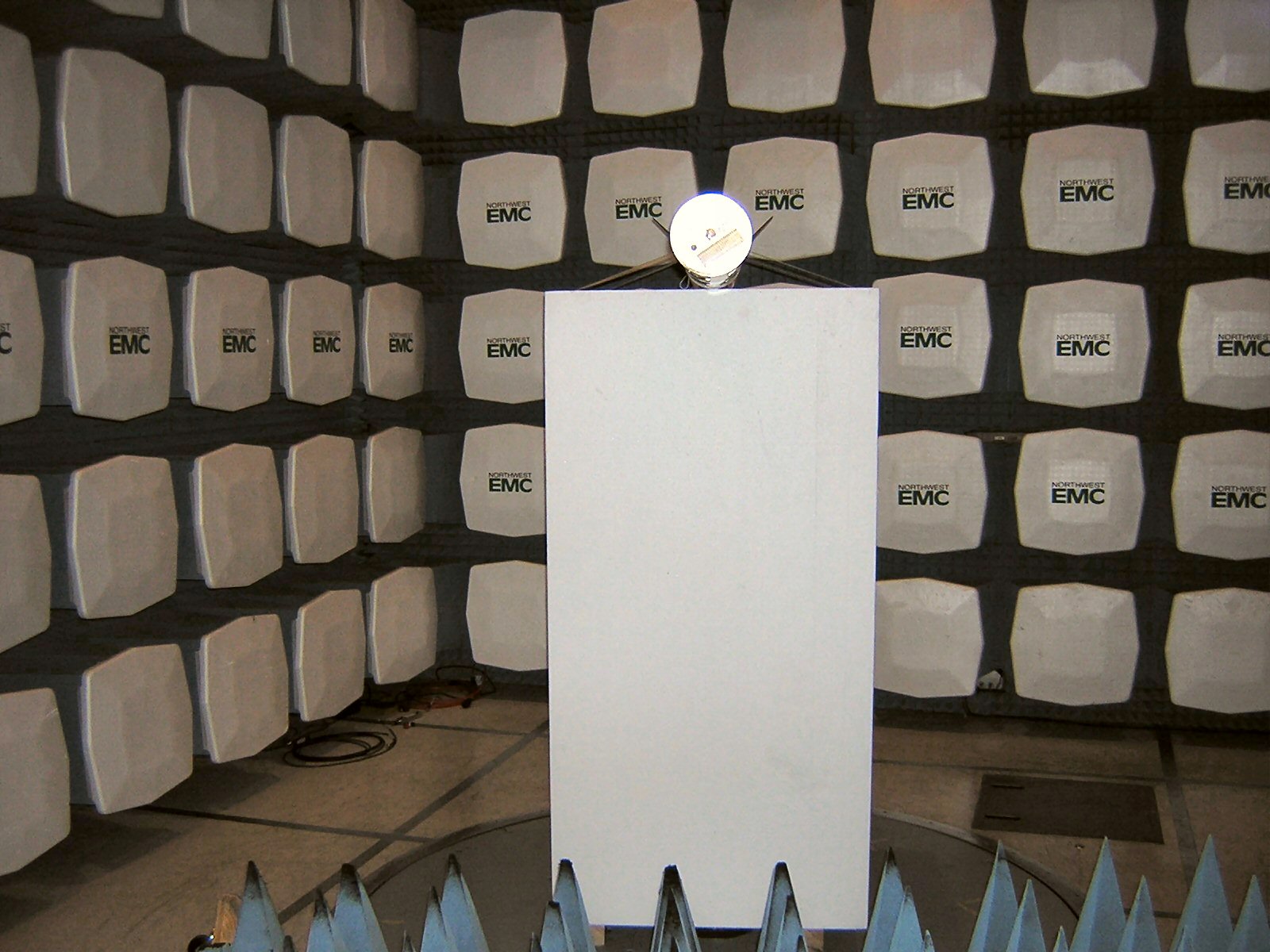
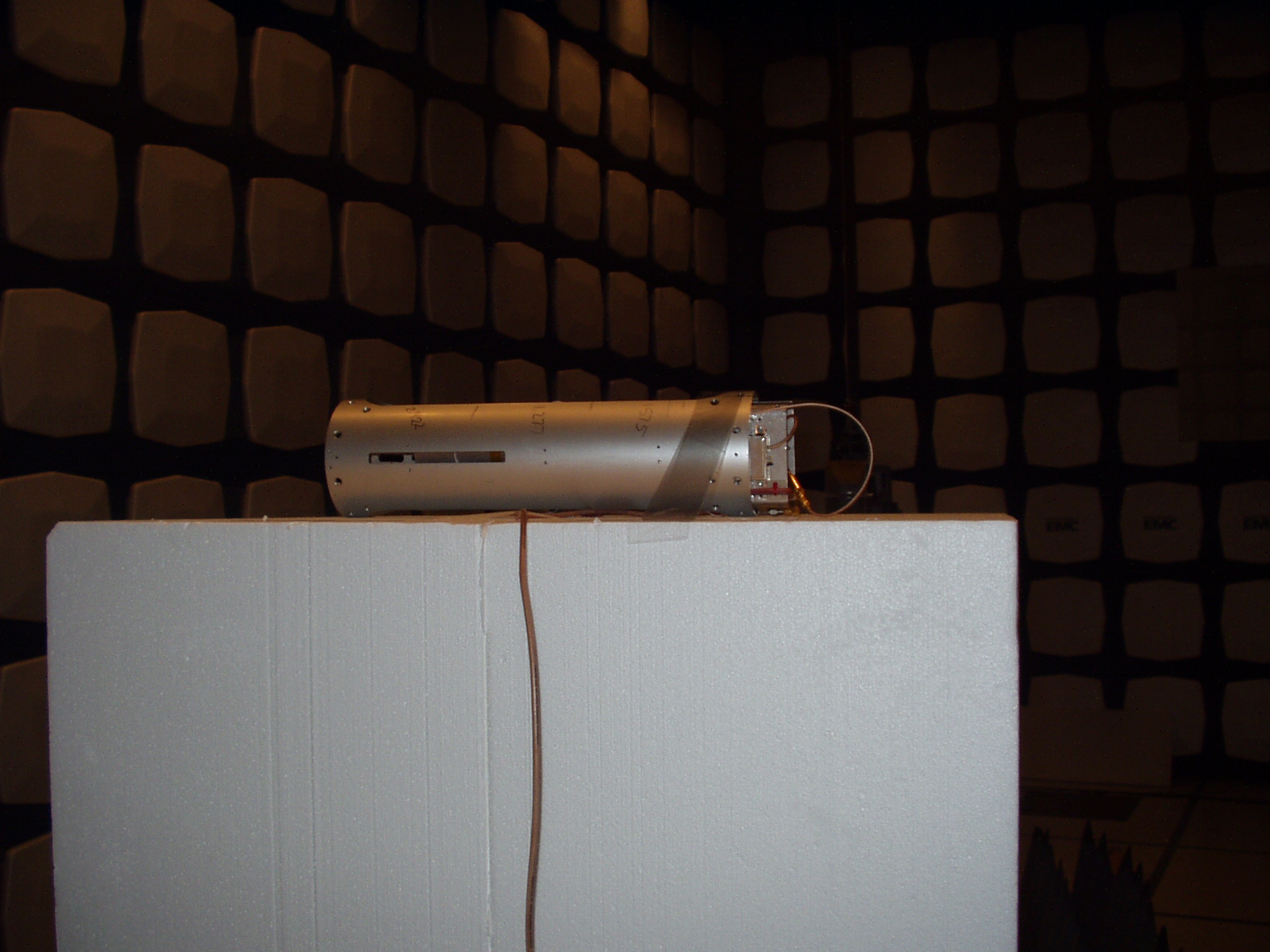
Photo of LV2.1 in Configuration 2 (which is similar to Configuration 3) from right in front of the receive antenna.
Reference Scans
Holly and Rod ran tests 1 - 5 in order to calibrate the chamber for absolute measurement.
WiFi Antenna
TEST 06: WiFi antenna, Configuration 2, RX antenna @ horizontal polarization
Changed height of receive antenna to the height of the center of the rocket: 1.77 m
TEST 07: WiFi antenna, Configuration 2, RX antenna @ horizontal polarization
TEST 08: WiFi antenna, Configuration 2, RX antenna @ vertical polarization
TEST 09: WiFi antenna, Configuration 3, RX antenna @ vertical polarization
TEST 10: WiFi antenna, Configuration 3, RX antenna @ horizontal polarization
TEST 11: WiFi antenna, Configuration 1 but rotated 180 degrees, RX antenna @ horizontal polarization
TEST 12: WiFi antenna, Configuration 1 but rotated 180 degrees, RX antenna @ vertical polarization
ATV Antenna
TEST 13: ATV antenna, Configuration 1 but rotated 180 degrees, RX antenna @ vertical polarization
TEST 14: ATV antenna, Configuration 1 but rotated 180 degrees, RX antenna @ horizontal polarization
GPS Antenna
TEST 15: GPS antenna, Configuration 1 but rotated 180 degrees, RX antenna @ horizontal polarization
TEST 16: GPS antenna, Configuration 1 but rotated 180 degrees, RX antenna @ vertical polarization
TEST 17: GPS antenna, Configuration 2, RX antenna @ vertical polarization
TEST 18: GPS antenna, Configuration 2, RX antenna @ horizontal polarization
TEST 19: GPS antenna, Configuration 3, RX antenna @ horizontal polarization
TEST 20: GPS antenna, Configuration 3, RX antenna @ vertical polarization
ATV Antenna
TEST 21: ATV antenna, Configuration 3, RX antenna @ vertical polarization
TEST 22: ATV antenna, Configuration 3, RX antenna @ horizontal polarization
TEST 23: ATV antenna, Configuration 2, RX antenna @ horizontal polarization
TEST 24: ATV antenna, Configuration 2, RX antenna @ vertical polarization
ATV Reference Dipole (1.253 GHz)
dipole @ 1.75m off ground
TEST 25: ATV dipole, RX antenna at same level and at horizontal polarization
TEST 26: ATV dipole, RX antenna at same level and at vertical polarization
TEST 27: ATV dipole, RX antenna at height maximized for signal strength and at vertical polarization
TEST 28: ATV dipole, RX antenna at height maximized for signal strength and at horizontal polarization
WiFi Reference Dipole (2.422 GHz)
dipole @ 1.75 m off ground
TEST 29: WiFi dipole, RX antenna at same level and at horizontal polarization
TEST 30: WiFi dipole, RX antenna at same level and at vertical polarization
TEST 31: WiFi dipole, RX antenna at height maximized for signal strength and at vertical polarization
TEST 32: WiFi dipole, RX antenna at height maximized for signal strength and at horizontal polarization
GPS Slot Antenna (1.575 GHz)
slot @ 2.05 m off ground
TEST 33: GPS slot antenna, "horizontal orientation" = configuration 1, RX antenna at same level and at horizontal polarization
TEST 34: GPS slot antenna, "horizontal orientation" = configuration 1, RX antenna at same level and at vertical polarization
TEST 35: GPS slot antenna, "vertical orientation" ~= configuration 2, RX antenna at same level and at vertical polarization
TEST 36: GPS slot antenna, "vertical orientation" ~= configuration 2, RX antenna at same level and at horizontal polarization
Found a loose connector, re-ran last two sweeps.
TEST 37: GPS slot antenna, "vertical orientation" ~= configuration 2, RX antenna at same level and at horizontal polarization
TEST 38: GPS slot antenna, "vertical orientation" ~= configuration 2, RX antenna at same level and at vertical polarization
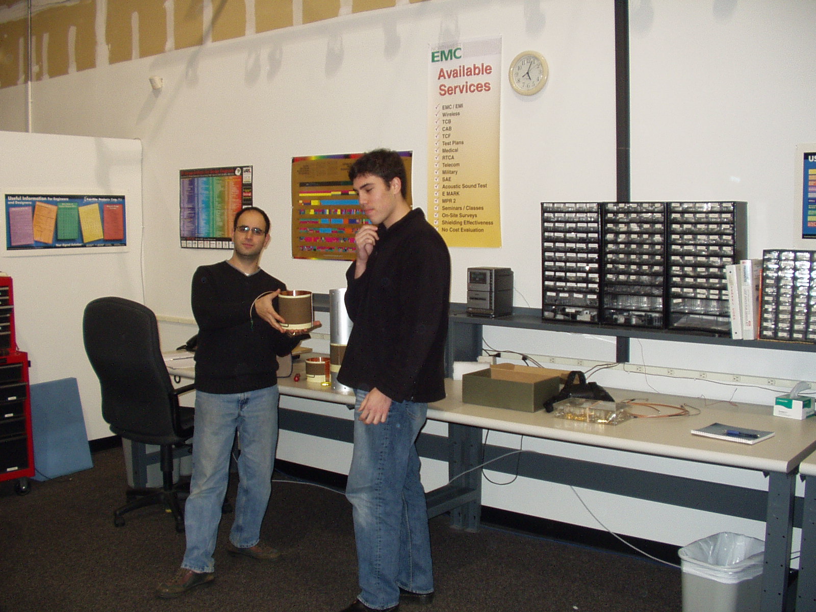
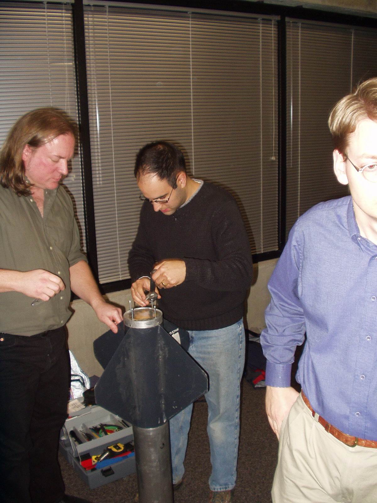
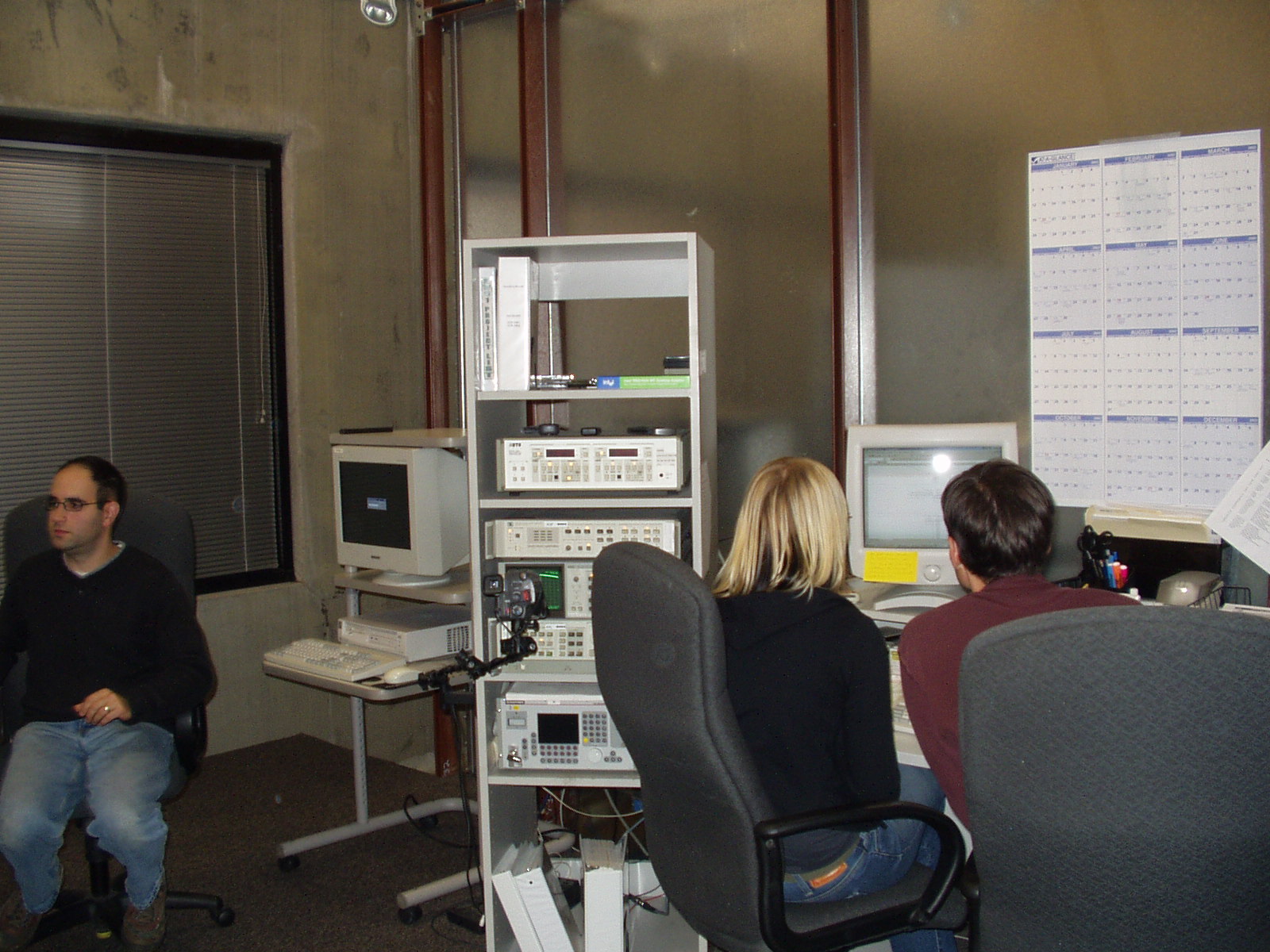
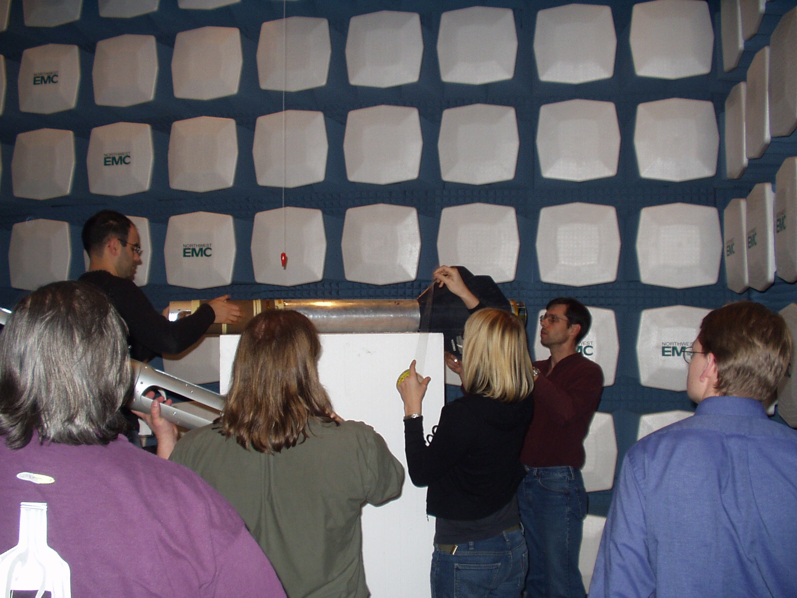
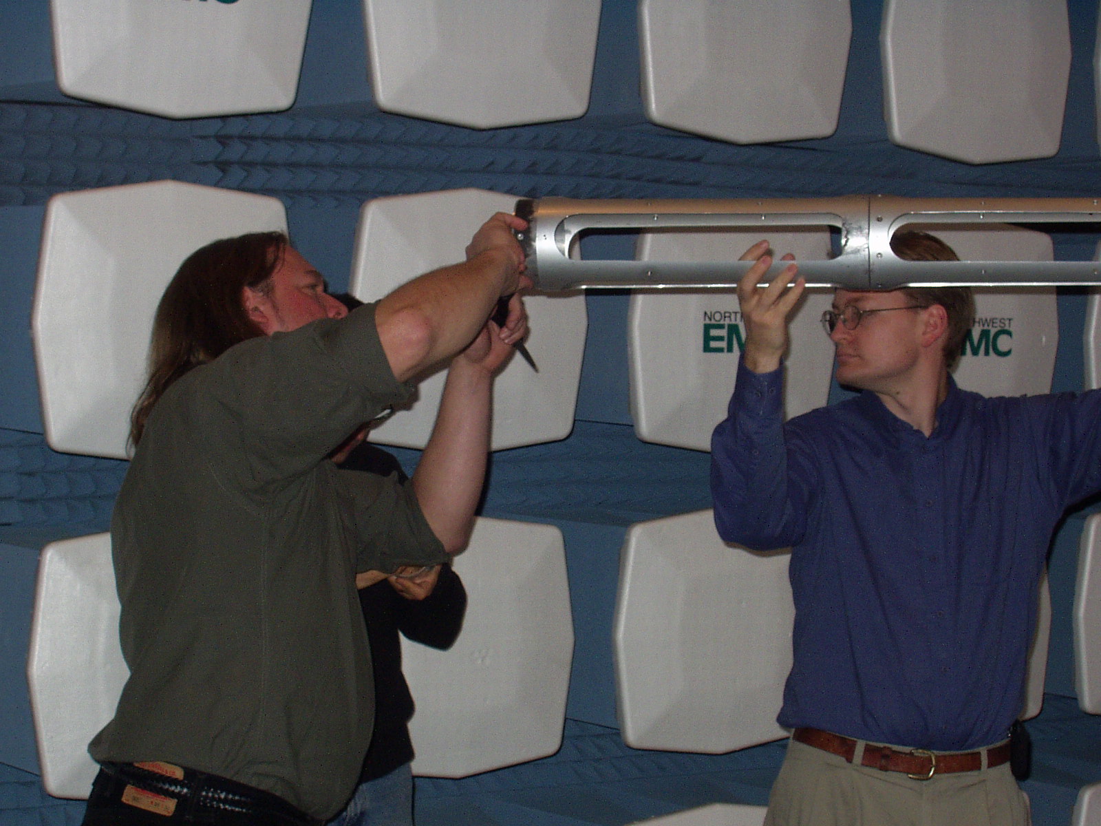
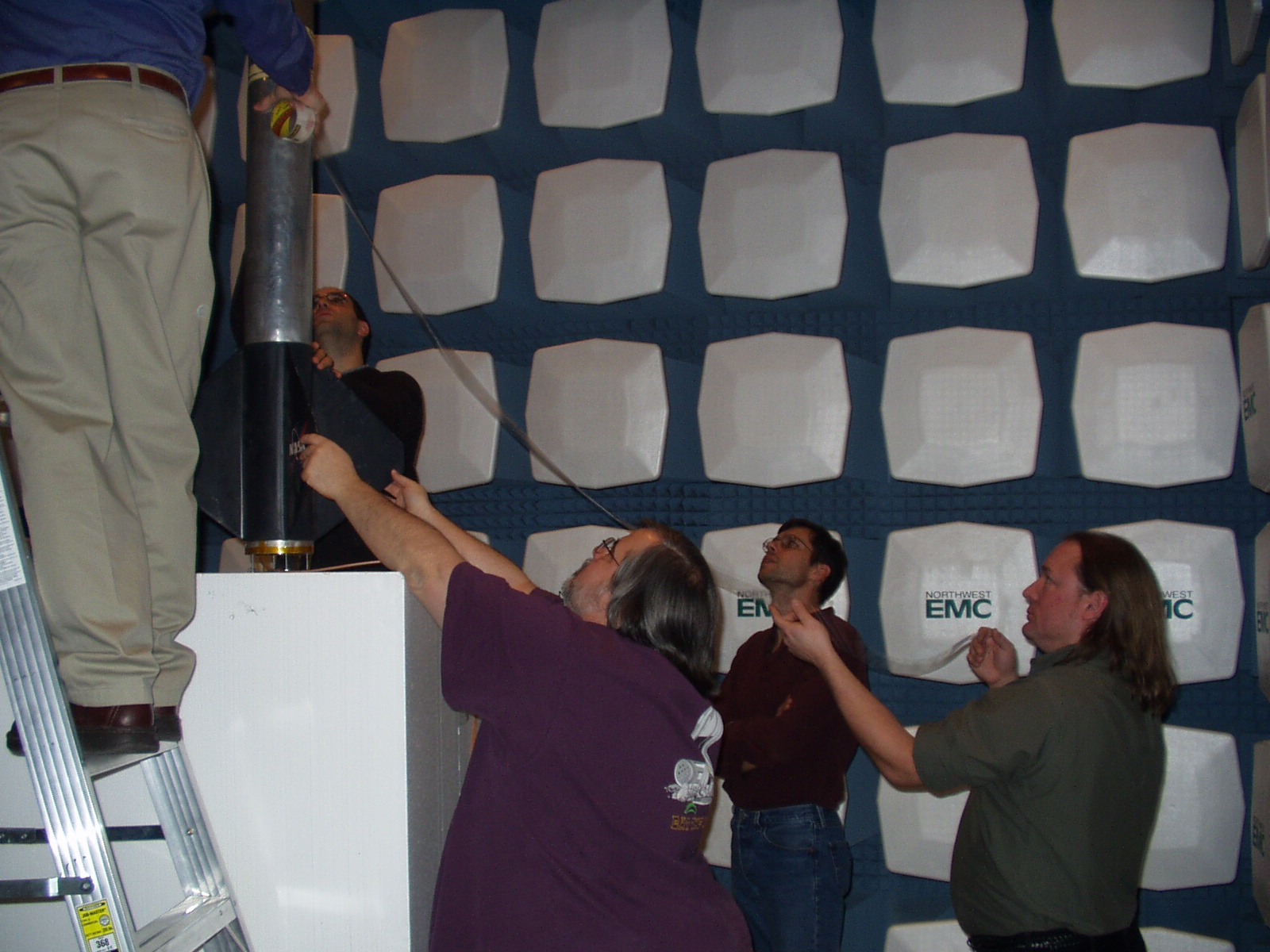
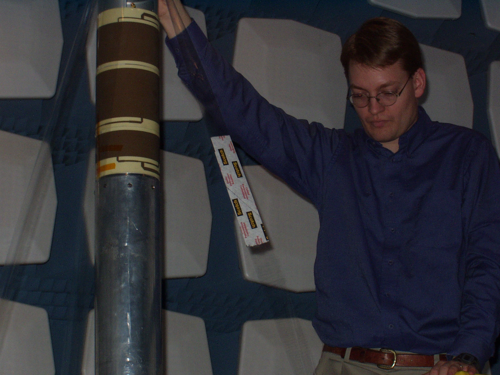
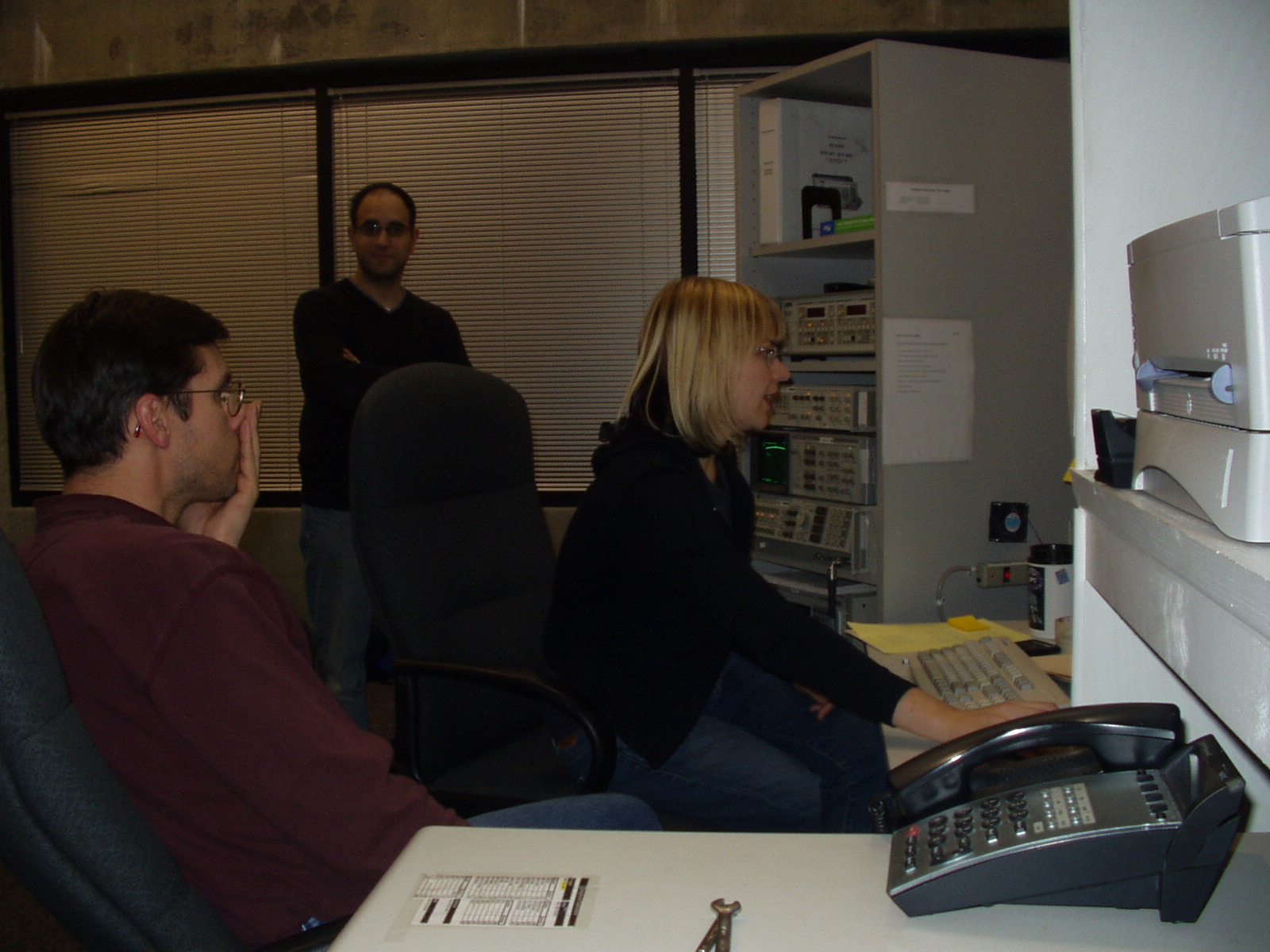
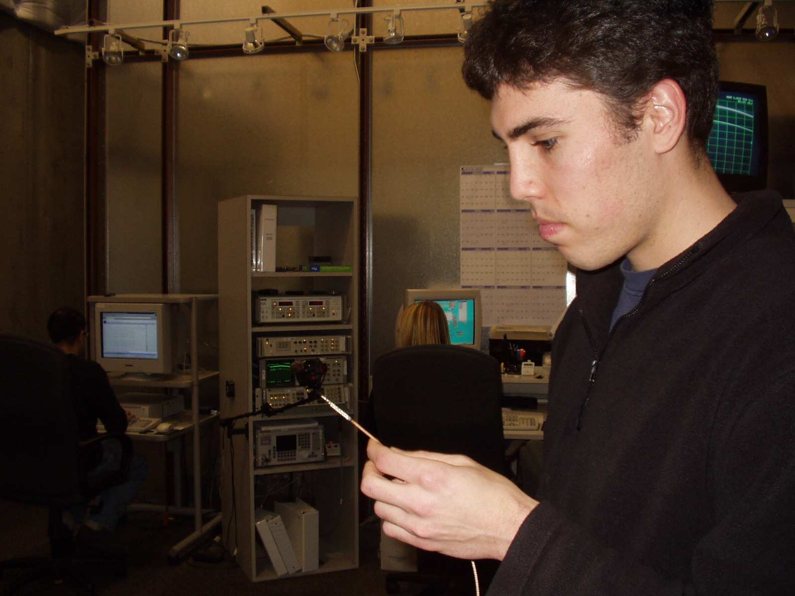
Gratuitous Pictures.
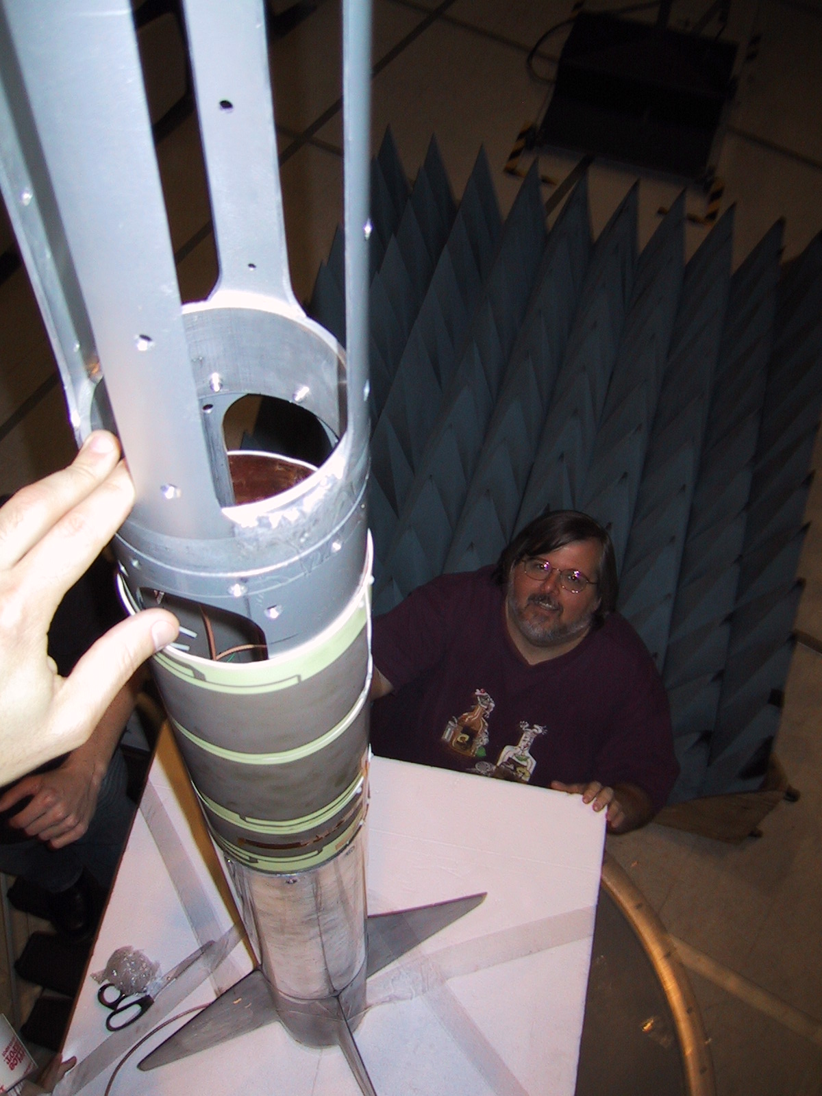
... insert more pictures here ...
Here are pictures taken with Glenn's camera
Okay; Which end is up?
Attachments: