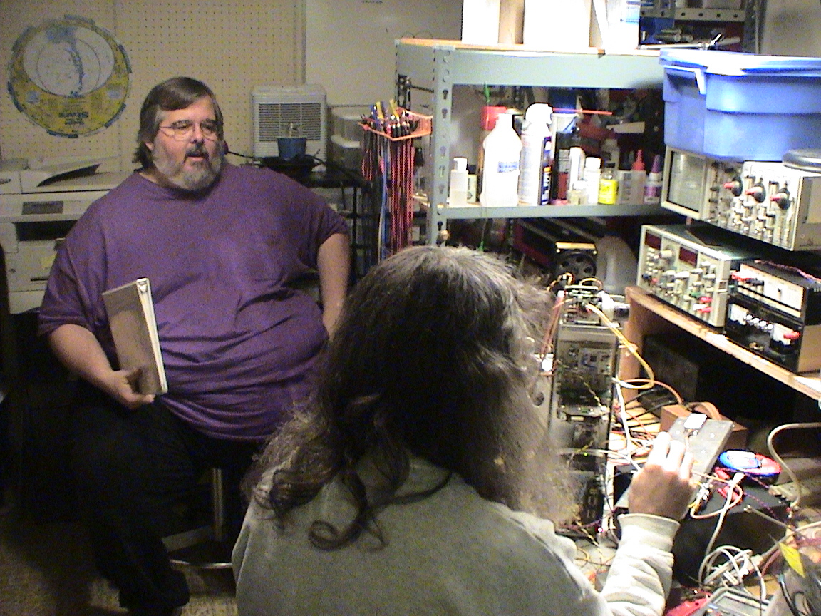
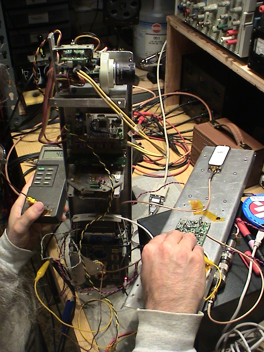
Summary: Tim, Tim R., Glenn and Andrew got together in Andrew's still disaster-zoned basement and measured the power consumption of each of the avionics system's components. Besides a few smoking Tantalum caps, there was no death and destruction - and shockingly, everything worked. Total power draw: 2.8 A @ 13.5 V = 38.4 W.
ATV System
We hooked up the ATV distribution node to the CAN King analyzer, but the node wouldn't turn on the camera via CAN message. Very weird, since it worked on the playa. But RC0 just wouldn't be set via CAN. So we hooked up the ICD2 and set the bits in the debugger.
Then we turned on the camera, overlay board, 1.253GHz "exciter" - e.g., transmitter, but everyone but Andrew thought "exciter" was better for some terribly wrong reason - and finally power up the 3W power amp. Even though we used a 50 ohm load as an antenna, we got enough leakage - even without the PA - to see the video image on a receiver a few feet away.
When we powered up the PA we got great results initially - until smoke started spiraling up from the power amp board. We thought for sure we smoked the M67715 PA, but instead it was a Tantalum installed backwards. Besides Tim R's bruised ego, nothing else was damaged. We replaced that one, blew another cap, and then finally everything just worked. We even ran it for 10 minutes just to see how fast it heated up the Al plate - it went from 30 deg C to 47 deg C in 10 minutes and didn't seem to get any hotter, which we thought was perfect.
We tried both the 6dB and 8dB attenuator, and decided to stick with the 8dB attenuator... (Glenn: why?).
ATV System max current draw: 1.55A
CAN Nodes
Then we powered up the IMU, GPS with preamplifier, and APS. Surprisingly, both the IMU and GPS didn't take almost any more power when spewing messages on the CAN bus at full rate... _maybe 1mA more. But of course the GPS did take plenty of power to run - including burning a lot of power through the 50 ohm load on the end of the GPS preamplifier since the GPS preamp passed DC to the load. Whoops. So we removed the load, and got, uh, better results.
IMU current draw: 70mA
GPS current draw: 125mA
APS current draw: 47mA
FC and Wifi
We booted the flight computer, fsck'd Andrew's Thinkpad's hard drive (isn't it always time to have to run fsck as root?) and started talking with the FC over 802.11b. The 802.11b was surprisingly power stingy; it really only used power when transmitting which is exactly what you want (i.e., is dependent on duty cycle).
So then we powered up the dreaded and highly abused 2.4 GHz +16dB amplifier. Surprisingly, it worked right off the bat. In fact, it was so good, we thought it was dead at first since it wasn't drawing more than about a 100mA. But then we realized the power consumption was based on (duh) duty cycle. So we scp'd /proc/kcore to the Thinkpad to simulate full bandwidth data... and then saw the 2.4 GHz PA start to draw some real power. It was great!
There's a 3 pin device - either a linear regulator or a MOSFET or something - which got really hot. Under no transmit loads, it hovered around 40 degrees C. But under the full 2MB/s load, it shot up to 100 degrees C and stayed there. _Future note: We think this should be heat sinked.
FC: 415mA
FC and Wifi w/PA: 1.05A
Conclusions
- Everything worked. Whoaahhh.
- Total maximum power draw: 2.85A @ 13.5V = 38.5W
- We hypothesized that a good launch would need only about 20 minutes of full power time: 2 minutes on the pad, 2 minutes to apogee, 15 minutes to the ground. But if something went wrong on the pad, or the main parachute was deployed at apogee, then this time could be extended to as long as an hour or more. We decided one hour to 50% depth of discharge was reasonable for a battery pack to handle: that's about 6 AHr.
- Our current batteries are not capable of handling 2.8A. Since they're 1.5AHr (rated at 2.5mA, whoops), we can't count on them being anything close to that 1.5A at 2.8/2 = 1.4A (for each set of two packs in parallel). So we decided that if we fly it with the Li primary batteries, we'll extend the pack out by another layer of batteries to fly 8 Li batteries together (700mA/battery pack, which is more reasonable for the Li to handle). Tim R. is going to test one of the Li batteries on an active load he's building so we can find out exactly how much we can expect from these batteries.
- After we revamp the power/battery document, we're going to choose a smart battery (think laptop battery) which we can use off the shelf with our own charger. This way we get the smarts of the smart battery - precision charge counter and SMBus (I2C) interface - and only have to build a charger to charge it. In fact, if we find a smart battery with Li Ion cells we know about, like the Panasonic 18650's, then we can always keep the smart battery controller and swap the cells if they die off. Tim R. is taking on the research and development on this "next gen" power system. Go Tim go!
Links
CanNodeSectionAppPower: Detailed component power listing (Tim R: please update).
BatteryPack: Battery pack discussion (Tim R: please update).