Avionics Workshop Meeting Notes 04/07/2002
In attendance: Tim, Andrew, Paul and Nate
Overview:
Yet another design day on the CAN nodes. Here's what we talked about:
References for the PIC Section:
We talked about zener voltage references versus buried zeners versus other devices. We're looking for something in a tiny SOT23 package - turns out there's a lot available.
We were concerned about the precision reference necessary to acheive less than 1 LSb error on the PIC's 10bit ADC across the industrial temperature range (-40C - 80C). It turns out after a bit of work (i.e., ridiculous algebra mistakes) we calculated that we need a tempco of less than 7.5ppm/degC. This is tight, but easily obtainable via Digikey parts (e.g., LM4010).
Tuning Local Oscillators:
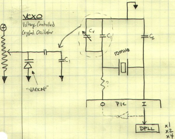
First we talked about tuning the local oscillators: in our case, the PIC18F458 will use a 10MHz crystal and with the onboard digital phase-locked loop (DPLL) multiply it by 4 to get 40MHz.
Although it's better to sync everything together (see below), tuning the PIC's main crystal oscillators could work as well. To do this, we'd need a variable capacitor to tune the crystal circuit to the right frequency. We can get surface mount variable caps, but they're twitchy and who wants something that's mechanical when you've got 15g's on launch. So we discussed tuning the circuit and then replacing the variable cap with a fixed one... but this is difficult since at these low capacitances (10's of pF) it's difficult to measure capacitance and there are all sorts of parasitics that make the variable cap different from a regular cap.
One solution is to replace the mechanical variable cap with the equivalent electrical version - the varicap. The varicap is a reversed biased diode whose PN junction acts like a capacitor whose capacitance is proportional to the voltage across it. So now we can tune the oscillator with a voltage, measure the DC voltage, and replace it with a few fixed resistors. Nice, but more components than the mechanical variable cap and another circuit to design.
Synchronizing all of the Switching Regulators:
Each CAN board has it's own Battery Voltage (~14V) to 5V buck converter. The buck converter chip we're using has it's own RC oscillator that drifts between 1.2 - 1.4MHz. The high frequency turns out to be good for small components and high efficiency, but we're worried that all of that noise in that 1.2 - 1.4MHz band will negatively affect the various radio receivers. In particular, the 2m DTMF uplink has IFs (Intermediate Frequencies) at 455KHz and 10.7MHz according to a phone call with Glenn. This seems ok, since 10.7MHz is at larger than the 7th harmonic of 1.4MHz, so the switching noise should be fairly attenuated. But after looking into the old GPS board specs, it turns out it has an IF of 1.27MHz - right in the switching band.
Note that since the buck converter chips are relaxation oscillators, you can synchronize them to a frequency that's faster than the fastest frequency they oscillate at - which would be at least 1.5MHz in our situation.
So we discussed many ways of syncing up all of the local oscillators on the board. We talked about threading a 10KHz line from the GPS to all of the CAN nodes, using a PLL and VCXO (voltage controlled crystal oscillator) to sync the 10MHz to the 10KHz, and then dividing that 10MHz down by 6 to get 1.667 MHz for the buck converter.
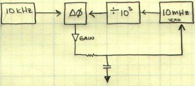
This would be a GREAT solution - we'd have all the converters and processors synched to UTC (what more could you want?). However, we don't have time for anything like this - designing a circuit like this could be weeks to months if it turned out to be harder than we imagined.
So we decided on a compromise - we'd run the buck converter off of the PIC's 10MHz crystal and get a switching speed of 1.667MHz with +/- 50ppm over temperature. With this solution, we sync the buck frequency to above all of the close IF's we know about, it only requires a divide by 6 chip (probably an SO8 PIC) and we can be pretty sure that all of the converters will be running at within a few kHz of each other.

System Power States:
We then talked about how we'd turn the damn thing on and off. This is more of a problem than you'd think - we don't really want an off switch which could fail during flight, but it's hard to turn on a circuit remotely once you've cut all power to it.
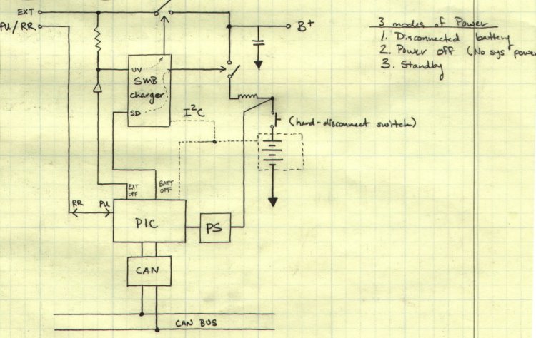
We came up with three power states:
1) Disconnected.
We physically disconnect the battery. In this case, EVERYTHING is off as long as the external supply is off. Obvsiouly, with the battery disconnected, we can't charge it (unless we rig up some kind of external charger).
2) Power Off.
In this case, the Smart Battery System/Umbilical PIC asserts the ?UnderVoltage (UV) and ?ShutDown (SD) lines on the SB charger chip. This effectively disconnects the rest of the avionics from the battery AND the external supply. Note that the SBS/Umb. PIC, battery charger, and SB electronics are STILL on even when the rest are off. Another problem is that you CAN'T charge the battery in this "Power Off" state since the UV and SD pins effectively disconnect the external shore power from the battery.
3) Standby
In this mode, the power is on but everything is in low power mode. The CAN nodes are sleeping, the RF amplifiers are off, etc. In this mode, we can charge the batteries.
4) On
Obviously, everything is running as necessary. We can be charging the battery as we run the avionics from ground power.
Future Avionics Meetings:
Paul and Nate have a conflict with Wednesday night meetings, so we're probably going to keep trying to work on Sundays from 11:00am - ~ 3:00pm.