CAN Bus Bandwidth Utilization
Choosing a Bitrate
Why did we choose 1Mbps?
'cause it's da fastest!
Although as you'll see we could run it slower, we can't think of good reason for us to go slower. We're really not worried about noise: we can always shield the CAN bus better if we start to get bus errors due to RFI, and we're not (yet) worried about EMF generation from the CAN bus at 1MHz being a problem.
And everyone knows the sad truth: we'll eventually need it. It'll be because of some sensor that requires a huge hunk of bandwidth, or because we need to minimize latencies in a control loop that has CAN-in-the-loop.
Calculating the Utilization of the CAN bus
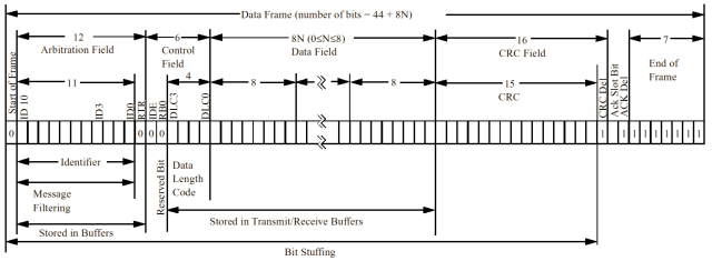
Figure 1: Standard CAN Message
Copied from Microchip's excellent CAN Introduction: "Controller Area Network (CAN) Basics", Application Note # AN713
Figure 1 is a very nice representation of a standard (11bit identifier, no errors) CAN message. You can see there's a minimum 44 bits/message, with 8bits for every data byte included in the message (duh). What's not obvious is the bit stuffing rule: for every 6 consecutive bits of one value (dominant or recessive), a single bit is inserted so that the DPLL (Digital Phase Locked Loops) of the protocol chips can sink to the bus. So the actual number of bits in a message is dependent on the message itself. You'd expect them to be fairly common since the bitstream is certainly not like a purely random stream... but it's one of those things where we'll just have to do the measurement when we have more time. And I suppose if we were really hurting for bandwidth we could even try and choose message IDs that don't have bit stuffing... but that's getting a little too obsessive for even us.
Other considerations for message bit lengths and rates are bus errors: any node finding an error for any reason will transmit an error frame which will kill the current message and add error frame bits. However, we'll stupidly ignore these kinds of problems in this analysis until we have some kind of handle on how many errors we see on the bus during actual operation. Theoretically - and certainly in our prototyping - they are extremely rare except during startup and shutdown.
Here's a rough estimate of how many bits CAN messages may use, and what we can expect, in terms of messages per second (mps), given those bit lengths:
| CAN Message Details | bits | mps |
|---|---|---|
| No data, No bit stuffing needed | 44 | 22,727 |
| No data, maximum bit stuffing (~6) | 50 | 20,000 |
| Average case: 4 bytes of data, 5 bit stuffs | 81 | 12,346 |
| 8 bytes of data, max. bit stuffing (~11) | 125 | 8,000 |
Notes: The bit stuffing figures (6, 5, 11) are just guesses and have not been very carefully thought out except that they look right given the general structure of the CAN message. You can also easily calculate the maximum and minimum latencies in transmission since a bit time is 1us.
LV2A Current Message Rate:
Here's the current estimate of the bandwidth needed for the LV2A system:
| Message | mps | kbps(1) |
|---|---|---|
| IMU Acceleration | 2,500 | 277.500 |
| IMU gyroscope | 833 | 79.135 |
| Pressure | 10 | 0.630 |
| Temperature | 10 | 0.630 |
| GPS (2) | 96 | 10.573 |
| ATV (3) | 33 | 3.663 |
| Power | 8 | 0.760 |
| Maximum misc. traffic | 100 | 7.900 |
| TOTAL | 3,590 | 380.791 |
(1) - Assumes 44 base + 3 stuffs + 8*N data bytes
(2) - Assumes 762 bytes/sec over virtual uart divided into 8 byte packets ~ 96 packets
(3) - Assumes 24 x 11 screen update each second = 264 bytes / 8byte packets ~ 33 packets
Which is of course only 38% of the 1Mbps bus. Not bad, really! Heck, we'll even be able to add Larry's Firewire digital video - over CAN! ;) Seriously, it's clear that the IMU takes up an enormous percentage of the bandwidth, and our plans for the IMU are to eventually go on the PC104 stack. Without the IMU, we're using less than 5% of the CAN bandwidth. This is good: soon we'll have to worry about latency issues due to control loops, at which point there's another layer of complexity in terms of timing messages for minimum latency (e.g., Time-Trigger CAN).