Who: Tim, Glenn, Jared and Andrew
New Mechanical Design
What we want it to do
Keep the cylindrical patch antennas on the rocket body while the rocket is going Mach 3... without complicating building the antennas. We need to be able to remove the antennas, because we expect our antennas to change and/or we expect to damage them in some really stupid way.
What we came up with
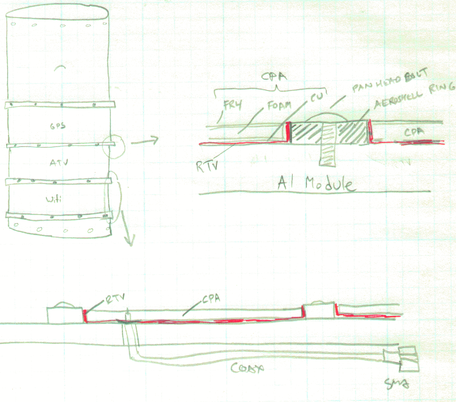
Along with the airframe team, we decided to replace the avionics module with a new module which doesn't have the two cutouts. This allows us to have a solid backing for the weak and flexible CPAs. So we're starting with a "blank module".
We also have bits of the aeroshell lying around that we cut away for the patch antennas. This is between 1/16" and 1/8" thick and made out fiberglass with some bits of carbon to make it black.
What we decided to do is to cut the aeroshell into ~ 1/2 inch wide rings. These rings will be on either side of the CPAs: that requires 4 rings all together (two on the outer edge, two to separate the three antennas). We screw the rings into the avionics module with pan head screws - and possibly even glue it down to the module. The copper/foam/FR4 antennas fit in between these rings. When we're testing and such, we just kapton tape around the antennas to keep them in the "slots" between the rings. When we're ready for flight, a few days before we use a nice RTV to "permanently" glue the antenna onto the Aluminum module. The RTV not only affixes the antenna but should also seal the gaps between the CPA and the rings, making an airtight, smooth antenna/ring structure.
What's really nice about this is that we don't have to affix the rings until the antenna design is really done, and moving the rings means just drilling more holes in the avionics module. And we don't have to affix the CPAs until a day or two before flight. And if they get destroyed, the RTV should allow us to rip off and replace the CPA (using, say, a razor blade to scrape off the RTV).
Benefits:
- Doesn't change our CPA design at all.
- Don't have to put screws or drill into the CPA structure.
- Rings can be moved for future antenna changes.
- Module and rings already exist.
Cons:
- After gluing, the antennas must be destroyed to be removed.
- After gluing, the antennas and avionics module are one piece so a stiff cover needs to be made to protect the antennas and the avionics module must be carefully handled.
- If an antenna is destroyed right before launch, it'll take at least 24 hours for the RTV to dry on a new antenna (use a heat-cured RTV?).
Next Steps for v3 CPA design
- Do a thickness and areal density measurement on a piece of foam.
- Tim does some analysis on what the hell's going on with the thickness thing.
- Andrew talks to the 3m FAE about the foam.
Based on these results:
- Depending on Tim's analysis of air pressure and our lameness, we do a team trip to Timberline lodge. We build the last v2 CPAs - a wifi and a gps - with the 8" wide PE tape at 6,000 ft (the lodge) or 7.000 ft (Silcox Hut) MSL. Everyone does dinner and maybe stays over night for fun.
- We test the antennas at PSU.
- We see how well the testing results fit into Tim's analysis
If the new "Hood" CPA's fit into Tim's analysis, then we're good to go to design the v3 CPAs (but we still won't be able to explain the flat CPA problem):
- Create a spreadhsheet for designing the CPAs and microstrips based on altitude and areal foam density.
- Have Circuit Images and Parks PCB make the v4 CPA PCBs. Only make two of each.
- Make up one set of three.
- Test them at PSU.
If they're ok, then:
- Make and attach aeroshell rings to the avionics module for the 3 antennas.
- Drill avionics module for the CPA coax and SMA's.
- A few days pre-launch, RTV on the antennas.
Playing with Squirrel Tape
We played with the 8 inch wide x 36 yds 3M 4466 polyethylene foam double-sticky tape. Wow, that's a lot of tape. Discovered that you can't use wax paper to protect the tape - eventually the tape removes the wax. We cut some pieces that Tim measured that Glenn will weigh to get an areal density measure... fun fun fun.
Measurement Data of *wide sample #2 from GNL
When I initially removed the backing from the sample and measured it, I noticed the weight decreasing at a rate of about 0.1 mg per second, with no end in sight! If this continues, I will have discovered antimatter! ;) This weighing was done about one minute after removing the backing. Something is evaporating here!
An hour later I went back into the lab and measured it again; Now the weight had truly stabilized as far as I can tell with this scale. I am not seeing any change after watching for about 1 minute.
| 1024 am | 1 minute after exposure | 2.6???g and decreasing |
| 1025 am | 2 minutes after exposure | 2.5904g and decreasing |
| 1135 am | 72 minutes after exposure | 2.2488g |
|---|
| Tare weight of boat | 6.7709g |
The perimeter measurements of wide sample #2 taken at the Feb.19th meeting are (clockwise) 2.9425", 5.9720", 2.9595", 5.9595" .
If we approximate the quadrilateral as two right triangles, the sample area is 17.605in^2. Thus the surface density is 19.8 mg/cm^2 .
