Introduction:
We made "flat" cylindrical patch antennas so that we could easily trim them down and tune them to the correct frequency. We made both the 1.575 GHz GPS and the 1.277 GHz ATV antennas.
We took them to the PSU Microwave Lab and trimmed them down with an xacto blade and ruler in order to get some sense of the dielectric constant as well as see if anything else was affecting the antennas.
See the bottom of the page for our conclusions.
1.575 GHz GPS Antenna
We started with the flat, untrimmed GPS antenna. F = 1.530 GHz, SWR = 1.11.
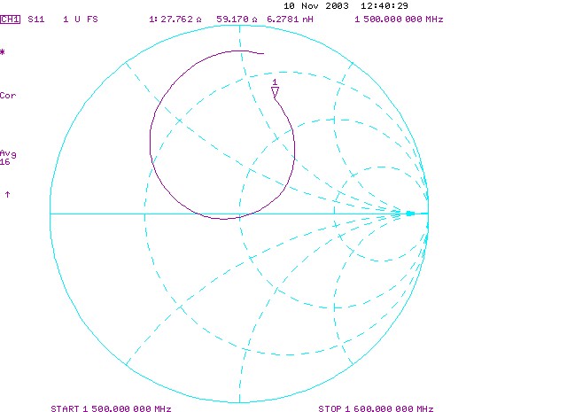
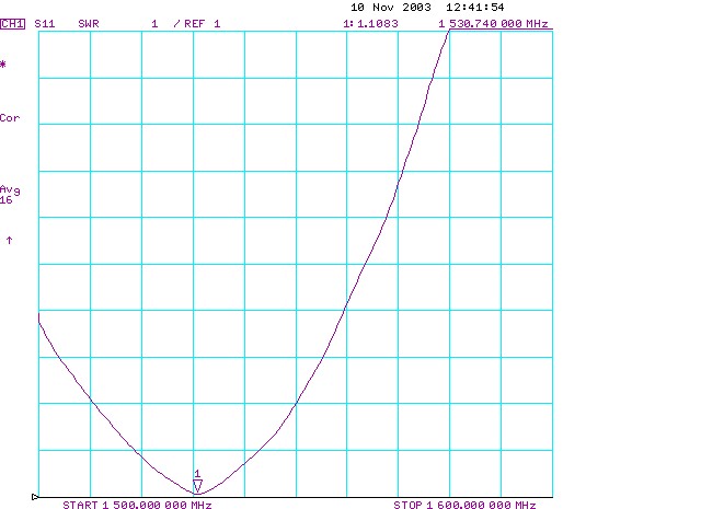
Untrimmed GPS antenna: smith chart and SWR plot
We trimmed the fiberglass off. F = 1.532 GHz, SWR = 1.11.
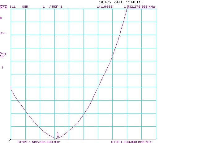
Trimmed GPS antenna: SWR plot
Tried to trim to 88 mm. Measured = 88.0 mm. F = 1.549 GHz, SWR = 1.07.
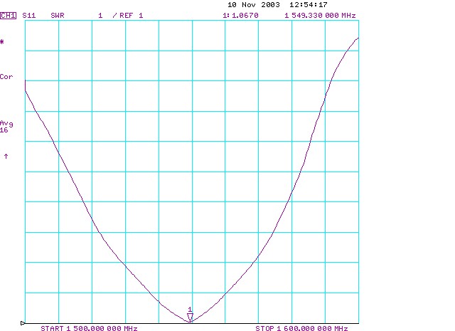
GPS antenna cut to 88mm: SWR plot
Trimmed to 87.5 mm (measured 87.43 mm). F = 1.558 GHz, SWR = 1.05.
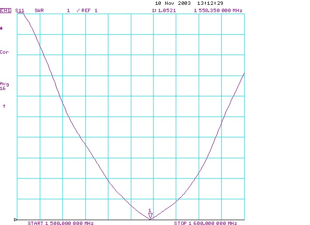
GPS antenna trimmed to 87.43mm: SWR plot
Trimmed to 86.52 mm (measured 86.7 mm). F = 1.569 GHz, SWR = 1.05, BW = 24MHz.
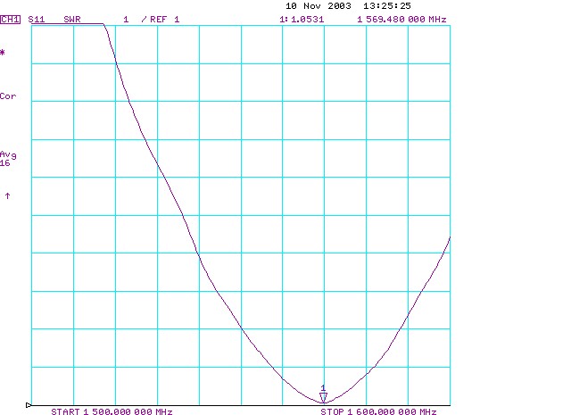
GPS antenna trimmed to 86.7mm: SWR plot
Burnished the edge with the xacto - tried to take off 0.1mm but it was pretty inconsistent. F = 1.573 GHz, SWR = 1.06.
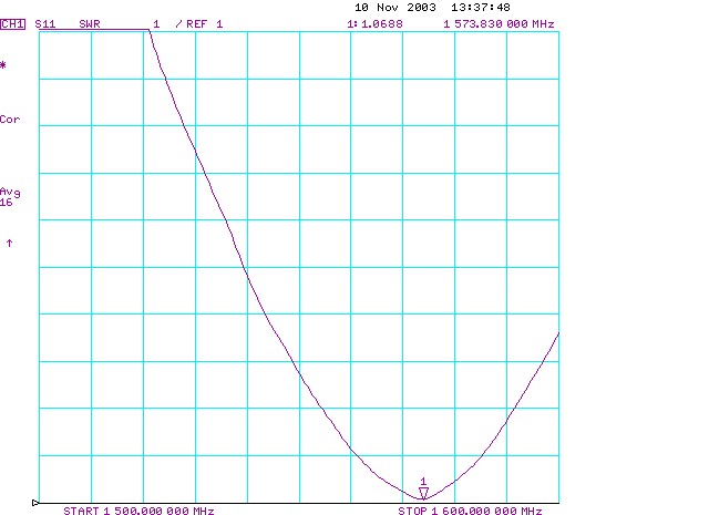
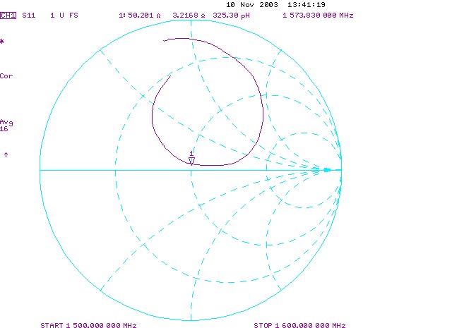
GPS antenna trimmed to 86.7mm and burnished: SWR plot and Smith Chart
1.277 GHz ATV Antenna
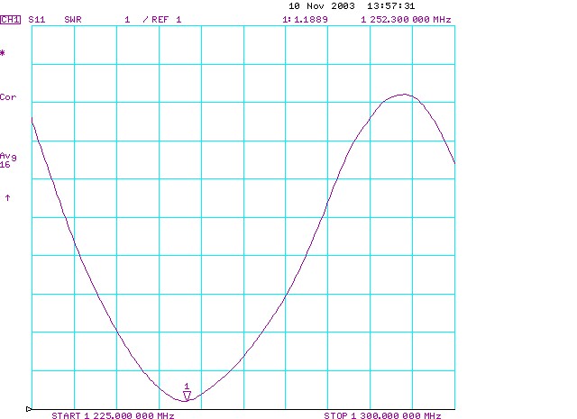
Untrimmed. F = 1.251 GHz, SWR = 1.16, BW = 15 MHz.

Untrimmed ATV antenna: Smith Chart
Trimmed off fiberglass. F = 1.252 GHz, SWR = 1.15.
Trimmed ATV antenna: SWR plot
Tried to trim to 108.65 mm. Measured = 108.6 mm. F = 1.265 GHz, SWR = 1.30.
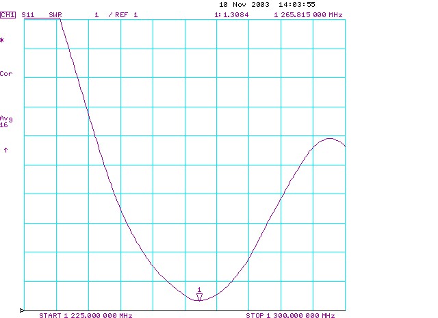
ATV antenna trimmed to 108.6mm : SWR plot
Tried to trim to 107.5 mm. Measured = 107.35 mm. F = 1.2785 GHz, SWR = 1.35, BW = 12 MHz.
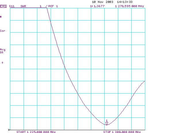
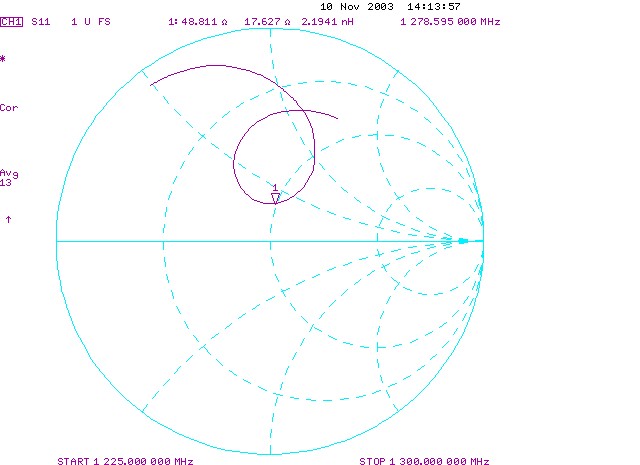
ATV antenna trimmed to 107.35mm : SWR plot and Smith Chart
Calibration Error
We discovered that our calibration for the HP 8753E Vector Network Analyzer might be invalid because we told the VNA we had the 7 mm calibration kit, not the 3.5 mm calibration kit that we actually had. We recalibrated it with the correct 3.5 mm setting, and retested the ATV antenna.
Recal'ed ATV antenna measurements: 1.2787 GHz, SWR = 1.34, BW = 13 MHz.
We concluded that we could mostly ignore the calibration mistake, since the ATV antenna measurements from the first calibration set and the new calibration set were so close.
GPS -> WiFi Antenna Hack
To get more points for Er of the foam, we decided to cut down the GPS antenna and make it a WiFi antenna.
Tried for 56.26 mm. Measured = 56.25 mm. F = 2.357 GHz, SWR = 2.21.
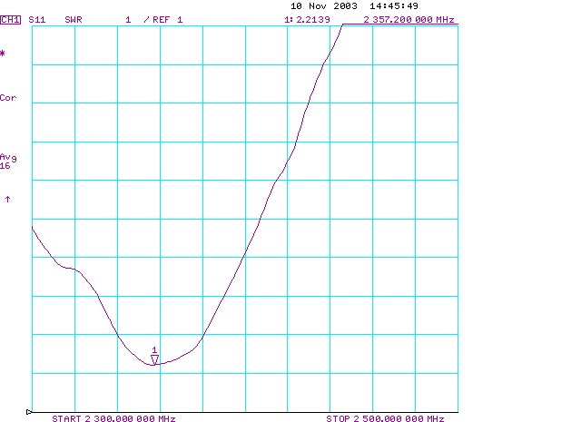
GPS -> WiFi antenna trimmed to 56.25 mm: SWR plot
Trimmed to 54.7 mm. Measured = 54.75 mm, but a little fat on one end. F = 2.408 GHz, SWR = 2.75.
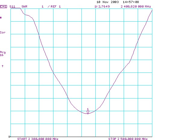
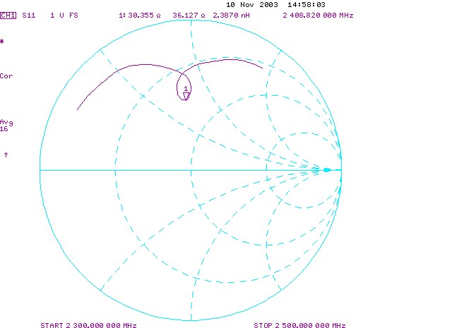
GPS -> WiFi antenna trimmed to 54.7 mm: SWR plot and Smith Chart
GPS -> WiFi -> 3 GHz Hack
We tried making a 3 GHz antenna by cutting down the GPS antenna further, using a Er = 1.280. Tried 44.18 mm. Measured = 44.25 mm, but fat on one end again. F = 2.879 GHz, SWR = 1.11.
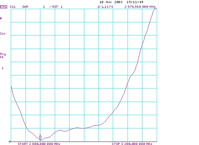
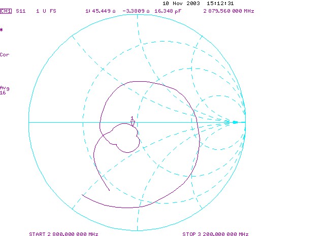
GPS -> WiFi -> 3GHz antenna: SWR plot and Smith Chart
Conclusion:
- The frequency dependence of the dielectric constant seems to be consistent.
- The unexplained variability on the antennas seem to be around 10MHz which is about 0.1 - 0.2 %... which doesn't seem terrible, but is not great.
Follow Up:
Each time the resonant frequency and length of a patch antenna is measured we define an effective dielectric constant (epsilon_r-eff) from this formula:
- L == lambda_0 / (2 * Sqrt(epsilon_r-eff))
Where L is the antenna length, and lambda_0 is the free-space wavelength at the measured resonant frequency (lambda_0 = c/freq)
The results of applying this formula to all our patch antenna measurements (current as of Nov.11 2003) is graphed below as epsilon_r-eff vs frequency.
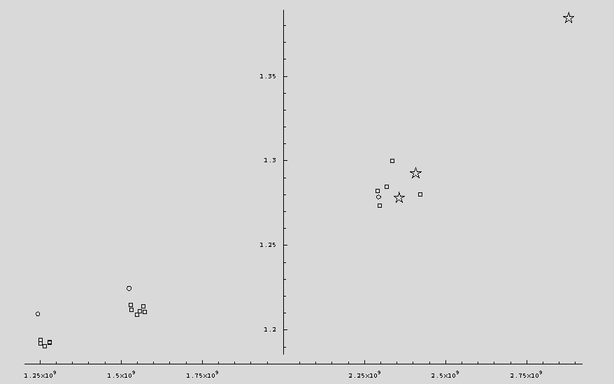
In the above graph, the three clusters of points represent our three antennas, GPS, ATV, and WiFi. The small circles (there are three of them) are the measured points for our first three cylindrical antennas which we constructed out in the desert. The three stars represent the results when we took our flat GPS test antenna and trimmed it down to a WiFi-ish length, and again when we trimmed it to something close to 3GHz. The remaining boxes are all successive measurements on the three flat test antennas as we attempted to trim them to their nominal design frequencies.
It is interesting to notice that the cylindrical antennas deviate more from the flat ones at lower frequencies, and that their resonant frequencies seem to be lower for a given length than the flat antennas. At least the first observation is consistent with theory, since the cylindrical antennas are "less flat" at longer wavelengths. (The last comment, though a correct statement, no longer seems a credible explanation for the observed variation. The cylindrical patches are basically insensitive to moderate variations in curvature (on the order of inches), while the dielectric appears to be consistently thicker in the 3 cylindrical patches vs the flat test antenna. The thickness variation appears to be a more important factor.)
The essential thing which is shown by this graph is a trend to larger effective dielectric constant as the resonant frequency is increased. There is no electromagnetic or geometric explanation for this, at least known to us, except that the dielectric properties of the antenna material itself vary with frequency.
The amount of variation observed is well within the normal range for polymer materials such as the foam tape we use as our inner dielectric. It's unfortunate that as yet we have no direct measurements of the dielectric constant vs frequency to verify this conclusion.
If we are right about what is causing the variation in epsilon_r-eff, then the best procedure for further antenna design would appear to be one using the measured values directly as the basis for new designs. This will be fine as long as the new antenna is for a frequency we have already measured.
It may be wise to include a factor to compensate for the antenna curvature. Ultimately it would be very wise to attempt direct measurements of dielectric constant vs frequency for our material.
The graph above wasn't very satisfactory so we recalculated it using an improved theory. The improvement is that we account for the fact that the impedance of the slot radiators is slightly capacitive. The resonating patch can be considered a transmission line between the two slots, with a characteristic impedance of about 1 Ohm. This transmission line transforms the capacitive reactance of the slot opposite the feed into an equal inductance at the feed position, the resulting parallel sum is purely resistive at the resonant frequency. The length of resonant patch to accomplish this is slightly less than one half the guided wavelength. (See Robert E. Munson, IEEE Trans. on Antennas and Propagation, Jan. 1974, pp.74-78.)
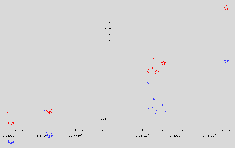
In this new graph the red symbols repeat the data plotted previously. The lower, blue symbols are the new calculations accounting for capacitive reactance in the slot radiators. In the new calculations, we try to back-propagate the geometric effects absorbed in the definition of epsilon_r-eff, and find the true material constant epsilon_r. The main effects of the new calculations appear to be lowering the estimate of the dielectric constant and making the cylindrical and flat test antenna results follow more nearly parallel lines. There also seems to be some flattening in the frequency dependence of the dielectric constant.
Lowering the estimated dielectric constant seems like a good thing because published values, and other estimates of polyethylene suggest numbers closer to the new values. Making the cylindrical and flat results more parallel seems like a very good thing because we still know of no mechanism to account for the frequency variation other than physical variation in the dielectric itself, and that type of variation should not depend on the antenna geometry very much at all.
The worst remaining problem is the offset between the cylindrical and flat antenna measurements. There are three obvious possibilities:
- Manufacturing variation
- Wrong slot impedance for the cylindrical case
- Bad measurements of the antenna geometry
Briefly, the process of wrapping an antenna vs building it flat may be changing the geometry of the dielectric. We are definitely using the wrong slot impedance. We are using the impedance for an infinite flat slot in the limiting case of slot height small compared to the free space wavelength, whereas we should be using the same value for the cylindrical case. These will be close, but we don't have the exact values. Last, now that we are trying to really nail the dielectric value to better than 1% accuracy, we need good measurements of the test antenna dimensions. Lumped along with this should be some observations of the effect on resonant frequency produced while changing the curvature of the cylindrical antennas during testing. (We have now done some tests where the curvature was varied by simply opening up the gap in the cylindrical antennas. The maximum opening tested was about 5 inches. The effect on resonant frequency is consistently very small.)
Attachments: