A lot of final design decisions were made at this meeting and tentative schedules set for prototype fabrication and testing. Design decisions based on simulations, testing, discussion and current trends in sounding rocket development have been ongoing with the airframe team in regards to LV2 for several months now. The vehicle has evolved significantly since last October but still remains true to the project goals and guidelines set forth at the projects conception and as outlined in the grant request for the Oregon Space Grant.
In attendance were: Tim Brandon, Roger Johnson, Maggie Kubit, and Brian O'Neel. Absent were; Kathy Moshner, Matt O'Neil, Matt Rupert, and Ray Woods
The Primary topics of conversation of the meeting were as follows:
1) Final Airframe Diameter Decision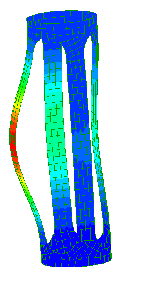
The vehicles diameter has changed many times in the past few months. Originally set at 6.25" OD, the diameter was changed to 5.25" after Maggie and Dr Zareh did the initial Finite Element Analysis revealed a boarder line value for the buckling load that a 6.25" module could fail at. This fact in conjunction with the propulsion team working on a 60,000 Ns motor with an OD of 5.36" it was decided to run an FEA and weight analysis on the 5.25" airframe modules. This proved to be the best diameter for the majority of our design criteria.
2) Avionics Module cutouts
Originally conceived as having four oval cut-outs to minimize weight and maximize accessibility, it was determined that 4 cut outs on the avionics module would not give us a large enough margin of safety for the buckling loads the module will experience on lift-off. Therefore the number of cutouts has been reduced to two for this module and thereby greatly increasing its strength and placing it in a region of high reliability with out too much of an increase in overall weight. The Recovery and Payload modules will still have the original 4 oval cutouts as planned.
3) Nose cone
Tim has done a lot of research into the optimization of the LV2 nose cone. The final decision for the nose cone is to go with a 'Parker' shape, which is somewhat similar to ¾ power equation but better optimized for our vehicle while traveling in the region of Mach 3-4. The aspect ratio of 7:1 was chosen due to manufacturing constraints.
The next step is for a prototype nose cone to be manufactured. Tim has already supplied the tabulated data to generating the curve required for this type of nose cone and Roger is investigating CNC options for turning down the Styrofoam nose that Brian will use to make a two-piece fiberglass female mold to be used for laying up multiple nose cones.
4) Aero-shell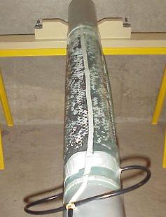
The aero-shell is the fiberglass tube that will slide over the modular aluminum airframe before flight. We have decided on a vacuum formed 8 layer Eglass sandwich that we have previously prototyped and tested in the lab to determine modulus of elasticity. The material looks good so far and will be fairly easy to fabricate.
We plan on laying up a small section for destructive testing next week, then a full section the following week like the one that will be used on the final vehicle.
5) Aero-shell attachment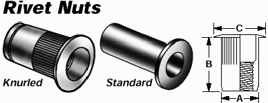
It has been decided that we will be using Riv-nuts to secure the aero-shell to the individual modules of the airframe. This will increase the overall strength of the vehicle and make it far less susceptible to buckling loads. The Riv-nut is an insertable fastener that is threaded. This will allow us to screw the aero-shell on to the frame with stainless steel screws and not have to worry about stripping the threads of a small hole tapped into the 0.125" thick module ribs. Maggie is researching the best fastener to use and is procuring samples. Brian is going to provide Maggie with maximum sheer loads generated by vehicle deceleration and parachute opening forces to help determine size and number of fasteners for not only aero-shell but inter-module connections.
6) Airframe module router and welding jig
In keeping with our philosophy of 'inexpensive' and 'simple' the airframe modules will be cut from the precursor tube that is used to lay up the fiberglass aero-shell. This will insure a perfect fit of the aero-shell to the modules. Once the modules are sectioned then they will have the excess material removed from them in the form of an oval that will be cut using a template and a 3hp hand router fitted with a 2-flute mill end. With the use of an appropriate jig to hold the pieces while being worked on the process should prove to be simple to perform and quick to setup and fabricate individual modules. The concept has been proven already with a high degree of success on a 6.25" prototype module. Brian will be working over the next two weeks to build the already designed jig. The jig will be multi-functional, it can be used for machining out the ovals and also it can be used to hold the fin and fin canister in proper alignment while the fins are being welded.
7) Fin Design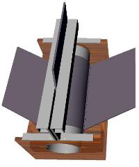
This is still being researched at the current time. It has been decided that we will use a fin canister to hold the fins and that this canister will slide over the motor casing. Ray, Tim and Roger are still looking at the geometry of the four fins.
9) Fin canister forward attachment
The fin canister will rest on a lip machined at the bottom of the motor casing while the rocket is under positive acceleration. Upon deceleration an acceptable method needs to be found to hold the fin canister in place. Methods for doing this are being investigated by Maggie, Brian and Tim. One possible solution involves a single fastener band clamp.
10) Securing aluminum welding services
Maggie is currently looking into options (individuals) that have the expertise to weld the fins onto the fin canister.
11) Module spacers
We will be using an elastomeric spacer approximately 0.10" thick in between the modules. The spacer will be compressed during assembly of modules and will help to damp down vibration between the modules. Roger is investigating acquisition of different material for this purpose.
12) Module compression method
The individual modules will need to be compressed together at time of assembly before the retaining fasteners are put into place. This will need to be done in the field so a simple method is being investigated by Brian.
13) Destructive testing of avionics module
A destructive test of one or two avionics modules will be scheduled for approx. 3 weeks from now. This destructive test will be used to verify our FEA analysis and to potentially see how much of an increase to our critical buckling load the addition of the aero-shell provides. Maggie will co-ordinate with Matt O. to see if we can arrange this.
14) Module coupling requirements
The different modules in the airframe can be place in different configurations depending on the mission. This flexibility is going to be more exactly defined by Brian in the next two weeks so that a precise method for coupling can be worked out.
15) Nose cone separation method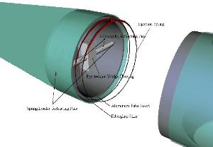
The nose cone must be deployed at apogee to release the drogue chute and possibly a payload. The exact method of the separation of the nose still needs to be worked out, but there are a couple of ideas in the works.
It was a very productive meeting and enough decisions were finalized and we have enough information to move forward on many systems in the airframe. We anticipate that over the next month a lot of physical hardware and prototypes will be produced as well as a lot of testing on the prototypes will be conducted.