LV1b Downlink Test
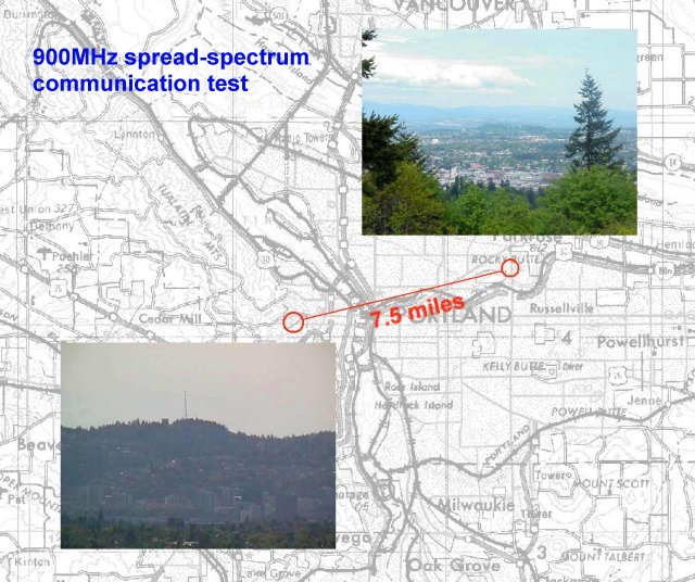
On April 30th and May 5th , 2000, Glenn, Tim, Phil, Adrian and Andrew met to try out LV1b's new 900MHz spread-spectrum 38.4kbps communications equipment. It's our fancy new telemetry system; we call it the "downlink" because it's a uni-directional communications channel from the rocket down to the ground station.
04-30-2000 Test #1
The 900MHz downlink was put together by Glenn back in September '99. At its core is a device called a "Linx Technologies HP Series-II Transmitter Module" (see http://www.linxtechnologies.com/). It's a small Radio Frequency (RF) module that takes analog or digital data in and sends it to a receiver module at 900MHz - around the same frequency as the new digital cordless phones. Although the top speed of the digital data is 50kbps, we're only running at 38.4kbps since that's the highest "normal" transmission rate we can comfortably get from most PCs. We could try a non-normal rate, but it's not worth the effort (pain, more like it) and the slightly lower speed should help with transmission errors.
The Linx transmitter module has only 100mW of output power, which is good for about 0.25 mile (line of site). To make sure we still get the signal at 12,000ft up, we've used a Motorola Power Amplifier to boost it to 1W. Since the 900MHz frequency falls into a Ham Band, as amateur radio enthusiasts we can do this sort of thing. You CAN'T do this if you don't have an amateur license. And you also shouldn't do this for long periods of time in the city since there are lots of electronic devices operating around 900MHz. So in our testing we tried to keep transmission times to a minimum.
Our Plan
Our plan was to send a random binary file from a one laptop computer, through the transmitter, to the receiver, and then into another laptop computer. We would then compare the original file with the received file to get an idea of the "bit error rate", or BER. In communications parlance this is a BERT (Bit Error Rate Test). So we made a few "random" 8bit binary files, with lengths of 1KB and 100KB file using MATLAB. We planned to try a local test and then drive up to Council Crest and Rocky Butte for a distance test.
The Reality
Of course, our plan was instantly and horribly crushed.
First, Tim and Andrew couldn't reliably transfer files from the laptop to the desktop using HyperTerminal in Windows 95. That killed an hour or so. Then we gave up, and went from HyperTerminal on Andrew's Windows 95 laptop to Kermit 2.3 on Glenn's DOS laptop. THAT didn't work and then we discovered we couldn't send raw binary files to Kermit. So we made new ASCII-only files using MATLAB. But even that didn't seem to work correctly. Turns out it was the old "CR" versus "CR+LF" problem and the data did actually transfer correctly, it just looked like it didn't.
After much finagling, and about an hour and half a wasted time, we finally ended up being able to send an ASCII file from Andrew's Windows 95 laptop running HyperTerminal to Glenn's DOS laptop using Kermit 2.3 over a serial cable with a null modem. At this point, we were ready to switch from the serial cable to the 900MHz "virtual cable".
Test #1: 15ft from the Dining Room to Living Room at 19.2kbps!
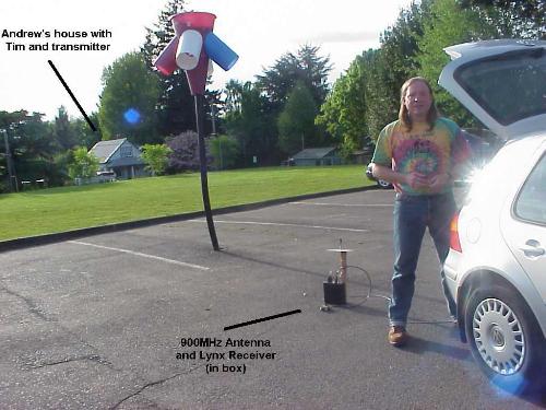
We first put the LV1b payload with transmitter on the dining room table, and put the receiver module (in a metal box) and antenna about 15ft away. Using Glenn's cool self-contained 8051 serial testing box, we burst data at 19.2kbps over the Linx modules from the dining room table to the living room floor (about 15ft) and into Glenn's laptop. There were a few transmission errors, but mostly where we expected them: at the beginning of the transmission. Because the Linx transmitter and receiver modules take a finite time to "startup", we knew that the first byte of the transmission would be garbled. What we didn't realize was that it could be the first few bytes! Although it mostly was the first byte, in some of the burst testing at 19.2kbps, we had several characters get garbled.
Test #2: 15ft from the Dining Room to Living Room at 38.4kbps!
We finally hooked up the laptop to the transmitter, and tried the first 38.4kbps test. Success! We were psyched. Much to our chagrin the dog would garble the signal as she walked back and forth wondering what all the excitement was about. Like Lassie, Kiah was trying to tell us something but we didn't find out until the very last test.
Test #3: 40ft from the Dining Room to the Sidewalk at 38.4kbps (success!)
Glenn hooked the receiver up to a battery (actually the LV1 12V power module which we removed from the payload!) and took his laptop outside onto the sidewalk. Success again! We had some errors, but we were picking up the signal.
Test #4: 300ft from the Dining Room across the Field at 38.4kbps (failed)
We then drove the Mobile Volkswagen Ground Station (MVGS) - Andrew's VW Gulf - around to the very end of the field that is directly across from the house. Using a cell phone, Glenn and Andrew called Tim back at the house and had him turn on and off the transmitter. We were shocked: we couldn't pick up any transmissions! and at only 300ft! We tried a few different things, and nothing seemed to help. With a Digital Multimeter (DMM) Glenn probed the RSSI (Receive Signal Strength Indicator) an we found only pathetic results: 800mV to 1.3V RSSI (2.5V was pegged on). What was worse was that even when Tim turned off the transmitter, the RSSI was still around 800mV.
We headed back to the house to see what we could do.
Negative logic on the Power Amp Power Level input
We milled about at the house, depressed about not receiving any signal. And then Glenn remember that the Power Amp power level input was *negative* logic - we had it hooked up to +5V, thinking that would turn on the power amp full blast. In reality, it turned it off! So we grounded the level input and BAM! The RSSI shot up to 2.5V.
Test #5: Try again on the sidewalk at 38.4kbps
We had an RSSI of 2.5V on the sidewalk. We received the data without a problem. Finally!
Test #6: 300ft from the Dining Room across the Field at 38.4kbps (success!)
With the Power Amp actually on, we went back across the field and tried again. Success! We got an RSSI of around 2.5V and we received the transmission with no problems.
05-05-2000 Test #2
Our Plan
Our plan was to send a 1kB and 100kB ASCII file from my laptop to Glenn's laptop via the 903.32MHz spread spectrum 38.4kbps LV1b Downlink transmitter and receiver. Later we would compare the original file with the received file to get an idea of the "bit error rate", or BER, of the downlink.
Andrew drove up to Council Crest (in the SW hills) and Glenn, Phil and Adrian drove up to Rocky Butte (near SE 95th and Sandy). The distance (as the crow flies; or in this case, as the RF field propagates) was about 39,400ft (7.5mi or 12km). That's a lot more than LV1's 12,000ft measured apogee, but we thought that if it worked at this distance, it would definitely work at the shorter distance.
Another factor was our antenna design. The inverted-V dipole antenna on the rocket, and the Turnstile Reflector (TR) antenna on the ground, are really meant for "free-space propagation". This means we expect the signal to be propagated with close to the rocket. In our tests, however, the rocket transmit antenna was only about 5ft above the ground. And the ground acts like a giant conducting plane (it is, after all, at "ground" potential!). So we expected that if we could get transmissions across with all of these factors, we'd be doing great.
The Reality
We gathered at 1:00pm, set off by 2:15pm, headed back to home by 4:00pm, and called it quits at 4:30pm. Andrew drove the Porsche up to Council Crest and set up everything - the payload, nosecone with antennas, laptop, etc - on the back of the car. It turned out that the Council Crest Drive wrapped right up to the top with a perfect view of Rocky Butte.
Glenn, Phil and Adrian didn't have quite as good luck. They had to park the car and hike up to a spot on the top of Rocky Butte in order to see Council Crest. Luckily they had a spare battery to lug up there.
People kept asking what we were doing, which was amusing. Next time we'll have to bring an extra person at each base camp just to explain to onlookers what we're doing! The best part was when a group of interested people stopped right in front of the transmitter in the direction of Rocky Butte during a test, effectively forming a wall of human attenuators.
Test #7: Transmitter: Nosecone pointing right at Rocky Butte.
Receiver: +12dB YAGI Antenna into a Signal Analyzer.
The first test we did was to see if we could see the transmitter at Rocky Butte. We could! We got a -60 to -70dB signal on our channel at Rocky Butte (on top of the noise floor which was about -110dB). The minimum the receiver needs to get a 10-6 BER (Bit Error Rate: e.g., 1 bit wrong in 1 million bits transferred) is -92dB so we had plenty of signal. And We totally forgot that the transmission antenna has four "nulls" (directions that very little signal propagate to) - one of which was straight out of the nosecone! So even in the middle of an antenna null, we could still pick up the signal
We were psyched!
Test #8: Transmitter: Nosecone pointing up w/antenna broadside to Rocky Butte
Receiver: TR Antenna, measuring RSSI from the Linx Receiver
We then looked at the RSSI - Receive Signal Strength Indicator - pin on the Linx Receiver while we keyed the transmitter up and down. Thee RSSI corresponds to how strongly we're receiving the signal from the transmitter. 0.8V is "no signal" and 2.5V is "full signal".
- Transmitter off: 1.3 - 1.4V
- Transmitter on (Low Power): 1.6V
- Transmitter on (High Power): 1.7V
We were pleased that we could see the transmitter being switched on and off through the RSSI. In general, these numbers were fine, but we should have gotten closer to 0.8V when the transmitter was off which was worrisome.
Test #9: Transmitter: Nosecone pointing up w/antenna broadside to Rocky Butte transmitting ASCII Files
Receiver: TR Antenna into the Linx Receiver into laptop
With these encouraging results, we tried a transmission test. When we plugged in Glenn's computer to the Linx receiver, however, we never got a quiet signal even with the transmitter off. Garbage would fill the screen, including control characters and what not.
We sent a 1kB file (1k.txt), and then a larger file, and although we saw that we were receiving it, we got tons of noise. We could tell because control characters were beeping, making the screen do weird things, etc. The received 1kB file was so corrupted that we couldn't even find the it in the 150kB of characters (1k_Received_05-05-00.txt - was 'b.b') that we captured on Glenn's laptop.
Test #10: Transmitter: Nosecone pointing up w/antenna broadside to Rocky Butte transmitting ASCII Files
Receiver: +12dB YAGI Antenna into the Linx Receiver into laptop
We put the YAGI antenna back on the Linx receiver and looked at the RSSI numbers. They weren't significantly different from the RSSI measurements using the TR antenna. This meant that everything up to the Linx receiver was working; it just wasn't quieting down for some reason.
We then tried to send an ASCII file with readable text (instead of random ASCII characters) across (Text.txt). We found the file, but it was horribly garbled (Text_Received_05-05-00.txt). Roughly 1 out of every 10 characters (10%) had one or more bit flips. You could still read it, but there were plenty of strange characters and other bit flips.
Test #11: Transmitter: Nosecone pointing in various directions
Receiver: TR Antenna into the Signal Analyzer
Finally, just before we quit, we plugged the TR antenna into the Signal Analyzer and keyed the transmitter up and down. Again, we got great results: about -70dB. On average, the TR antenna was -5dB less than the +12dB YAGI antenna, so we think that the TR antenna has about +7dB of gain.
We then tried pointing the nosecone in different directions. With the antenna broadside to Rocky Butte, we got about -65dB. With one antenna pointing towards Rocky Butte, we got about -85dB. This is great since even at the null we're getting above the -90dB power limit.
Summary:
Everything worked beautifully up to the Linx receiver. We got plenty of signal strength over the 39,000ft from Council Crest to Rocky Butte from the transmitter. But, for reason, the receiver picked up tons of noise on the receiver and it never quieted down.
We hypothesize that although the signal analyzer showed a -110dB noise floor on our 903.2MHz channel, some other 900MHz signal near Rocky Butte was swamping the receiver. This would explain why the RSSI never dropped below 1.3V and why we received so much noise on top of our signal from the transmitter.
|
Download this report in .pdf version LV1bDownlinkTest.pdf |
Communication Systems Test Photo's:
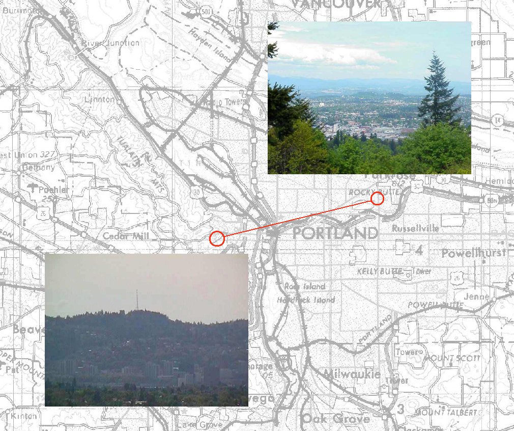 |
7.5 miles from Council Crest to Rocky Butte! | 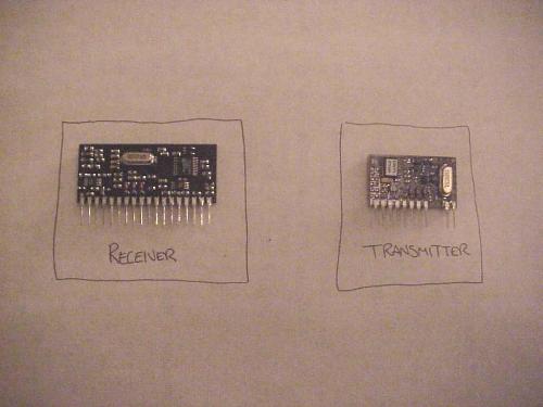 |
The Linx Transmitter and Reciever. |
| Linx transmitter in LV1b payload frame. | 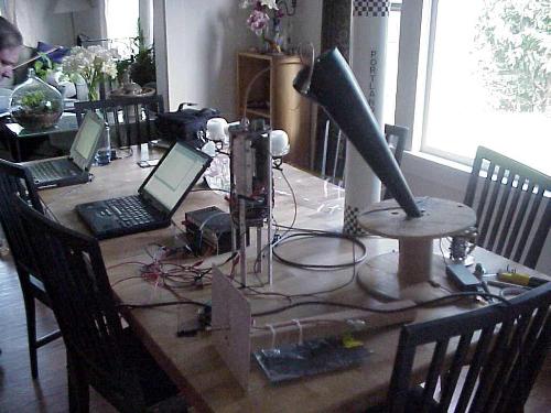 |
Test equipment layed out for serial cable test. | |
 |
Short range test. |  |
Glenn recieves data on short range test. |
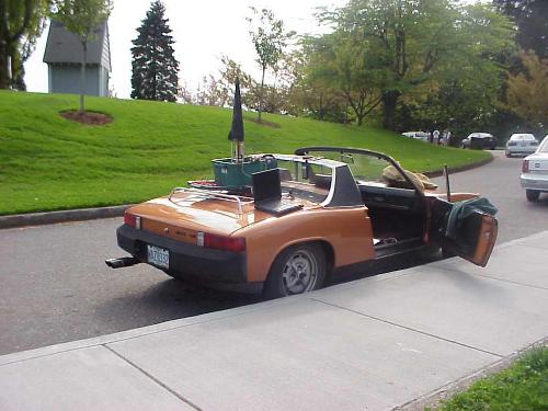 |
The Mobile Porsche Ground Station at Council Crest | 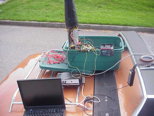 |
A closer View. |
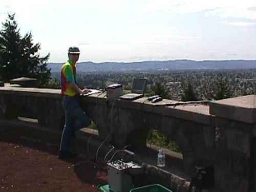 |
Phill recieving data at Rocky Butte. |