ETHERNET CONNECTOR
Overview
The purpose and reason behind the design of a separate Ethernet connector to interface with the flight computer carrier board was the economy of space. Because the flight computer carrier board was to be minimized in size, while still keeping lots of essential features hence components, we decided to design the ethernet as an off board module since it didn't really to be on the board while in flight.
Part Description
Ethernet Transceiver
Part #: DP83848C
DIGIKEY Part#: DP83848CVV-ND
Unit Price: $6.8
Package: 48-LQFP
DC Input Voltage: 3V~3.6V
RJ45
Part #: J1026F21CNL
DIGIKEY Part#: 553-1351-ND
Unit Price: $6.59
Package: Panel Mount; Through Hole, Right Angle
Speed: 10/100 Base-TX
LED Color: Yellow - Green
Crystal Oscillator
Part #: ECS-250-20-33-TR
DIGIKEY Part#: XC1142DKR-ND
Unit Price: $3.57
Frequency: 25Mhz
Mounting Type: Surface mount
LED
Part #: LG L29K-G2J1-24-Z
DIGIKEY Part#: 475-2709-2-ND
Color: Green
Unit Price: $.16
Forward Voltage: 1.7V
Current: 2mA
Functional Description
Integrated Circuits
IC1
Chosen for its relatively small size (7mmx7mm). Low power consumption, availability of feature such as Media Independent Interface (MII) as well as Auto-MDIX for automatic detection of required cable; it also supports 10Mb/s and 100Mb/s data transfer mode as well as Half/Full-Duplex data transfer mode which are all supported by the MPCxxx.
XTAL
This external surface mount crystal oscillator is a 25Mhz crystal (recommended by the Ethernet Transceiver datasheet)
LED1
The LED is SPEED LED. It indicates the speed of the device. It would turn on to indicate 100Mb/s and stay off to indicate 10Mb/s
Resistors
R1, R2, R11
These resistors are used to strap the device to operate in AUTO NEGOTIATION WITH 10/100 HALF/FULL DUPLEX ADVERTISED mode. This mode allows the device to select the most efficient data transfer speed and type, as opposed to the FORCED mode. The datasheet recommend to use 2.2k for strapping resistor values.
R3
This is a current limiting resistor. R3=(3.3V-1.7V)/2mA, (LED Forward voltage=1.7V, Forward current = 2mA)
R4
This resistor is a 4.87k pull down resistor. It's a bias resistor connected to pin 24 (RBIAS) of the Ethernet transceiver. It's value is recommended by the transceiver datasheet.
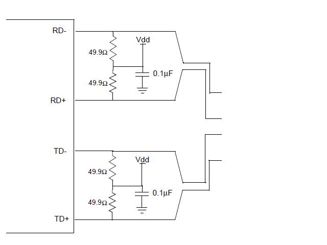
R5, R6, R7, R8
These resistors are impedance matching resistors for a twisted pair interface. Their values were strictly picked out of the datasheet.
R9 and R10
These 2.2k are pull up resistor to the 3V3 source connected to pin 20, 21 as recommended by datasheet
R12
This is a zero ohm resistor (optional).
Capacitors
C1, C10, C11
Used as decoupling capacitors for noise suppression at the power pins of the transceiver.
C2, C3, C4, and C5
These capacitor values were chosen to be same as the model used on the datasheet.
C6, C7, C8, C9
These capacitors are noise suppression capacitor connected to Power Feedback Output and Input pins. Their values were picked strictly with respect to the datasheet recommendation. It is recommended to use a tantalum capacitor for C6; and to connect C6 and C7 as close as possible to the Power Feedback Output pin 23.
C13, C14
Load capacitor of the crystal with 20pF capacitance.
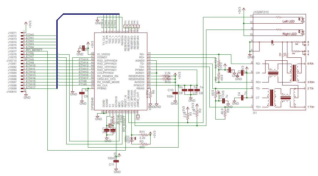
Schematic