CAN TRANSCEIVER
- Manufacturer part#: SN65HVD235
- Digi-key part#:SN65HVD235DG4-ND
- Package: SOIC
- Voltage Input: 3-3.6V
- Unit Price:$4.3400
Functional Description
Pins
Connecting the RS pin (pin 8) to ground through resistor R1022 allows us to select high speed as our mode of operation.
Integrated Circuits
U1008
This is the Controller Area Network transceiver.
Resistors
R1022
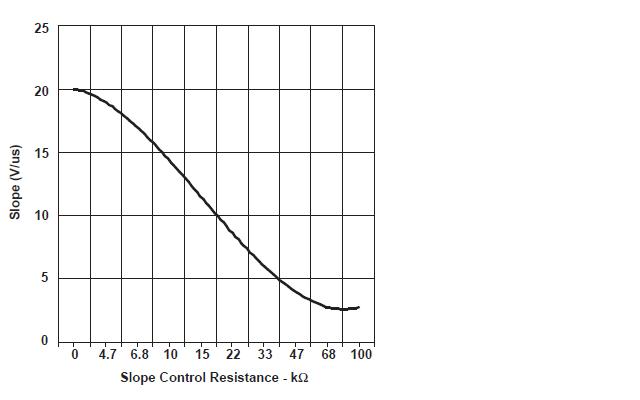
This resistor sets the slope of the rise and fall of the driver output signal.
For this project we simply used the design the 2009 Capstone team used (we didn't see a need for changing it.)
In that design, they chose the value of R1022 to be 18K which can be deduced from the graph of the Driver Output Signal Slope vs Slope Control Resistance Value (fig 31 on datasheet)
R1025
Bus termination is used to minimize signal reflection on the bus and improve EMC performance. ISO-11898 requires that the CAN bus have a nominal characteristic line impedance of 120Ω. Therefore, the typical terminating resistor value for each end of the bus is 120Ω.[1] (Not sure why a 60 Ohm resistor was recommended instead.)
Capacitors
C1030
This is a bypass capacitor for noise suppression, burst smoothing between Vcc and GND
Note
The whole block made up of U1007, C1028, C1029, R1024, R1023, R1021, D1000D and D1001D were entirely adopted from the 2009 Capstone.
Reference:
[1] ww1.microchip.com/downloads/en/AppNotes/00228a.pdf