Electrical Test of the Quest Electric Match (Pyrotechnic Igniter)
Portland State Aerospace Society <www.psas.pdx.edu>
The firing energy and fusing energy of the "Quest Q2 Model Rocket Igniter" electrically operated pyrotechnic igniter are characterized using a high bandwidth digital storage oscilloscope and pulse-triggered high speed MOSFET switch. The results are consistent with the theory that ignition occurs once sufficient electrical energy has been deposited. From the data the approximate minimum energy to fire an igniter is calculated. Tests were done using both a 12 W and 1600 W ignition circuit. Independent of ignition power, depositing approximately 1 joule of electrical energy is sufficient to ignite the device. More energy than this can be deposited, however eventually the tiny bridge wire inside the device will open like a fuse preventing further current flow. This has been observed to happen when about 3 J of electrical energy have been deposited. In all tests, the energy required to ignite the pyrogenic material was substantially less than the energy needed to fuse the bridge wire. In fact, in all minimum firing energy tests the bridge wire remained intact even though the pyrogen burned to completion.
Preliminaries
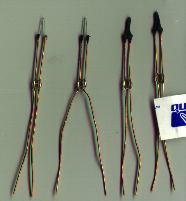
Fig.1
Figure 1 shows 4 Quest Q2 igniters <www.questaerospace.com>(Item number 7022). The two igniters on the left have had their pyrogenic material removed to show the underlying bridge wire. The overall length of a Quest igniter is about 2 inches. The manufacturer specifies a firing voltage of 6-9 volts. Q2's are priced at about 83¢ each for small quantities (2007). The manufacture doesn't appear to specify no-fire, or all-fire currents, or a typical resistance. Quest Q2 igniters are made in China.
Referring to figure 1, the igniter second from the left (igniter #11 in our tests) has actually been previously fired. Note that its bridge wire is still intact. The igniter on the far left has had its pyrogenic compound mechanically removed. This was done in order to detect if the chemical action of firing was eroding the bridge wire (it wasn't). Before firing the DC resistance of igniter #11 was a measured as 2.3 Ω, after firing the DC resistance decreased to 1.25 Ω. Based on a single igniter the meaning of this resistance change is unclear.
As can be seen in the figure, a Q2 igniter is built around its bridge wire. This is a short piece of thin high resistance wire that electrically connects two larger copper wires. The effect of this arrangement is that most of the power dissipated when passing an electrical current through the igniter emerges from the bridge wire. To complete the igniter assembly the bridge section is dipped in a pyrogenic compound. Based on the sparkler-like emissions produced when firing a Q2 igniter, this compound probably contains a small percentage of aluminum.
The bridge wire is approximately 0.4" long and 5 mils in diameter (about 36 gage). The copper lead wire is approximately 26 gage and is bare. The innovation of the Q2 is that it uses a small molded glass bead to stabilize the copper wires. This is a more robust design than an Estes-style igniter, which relies on the brittle pyrogen to keep the wires in position. The connection between the copper wire and the bridge wire is made by folding the copper wire over at its end, placing the bridge wire in the fold, and smashing the ends of the copper wire together. As far as can be determined by casual inspection, this crimp connection seems well made, and should not be a large source of reliability problems.
As a beginning point for testing, the DC resistance of a dozen Q2 igniters was measured. The results are shown below.
|
Igniter # |
1 |
2 |
3 |
4 |
5 |
6 |
7 |
8 |
9 |
10 |
11 |
12 |
|
DC Resistance [Ω] |
1.5 |
6.1 |
2.6 |
47.9 |
2.7 |
6.3 |
4.9 |
1.8 |
2.1 |
2.4 |
2.3 |
4.5 |
Table 1
There is a surprisingly large variation in resistance. Furthermore, some igniters (such as #4) displayed a resistance that seemed to vary if the igniter was flexed slightly. Despite this, all the igniters tested (including #4) fired at approximately the same energy. For applications where reliability is important, Q2 igniters need to be pre-screened for DC resistance. Only igniters in the 1-3 Ω range whose resistance is insensitive to mechanical agitation should be used.
The test firing circuit we used is shown in figure 2. 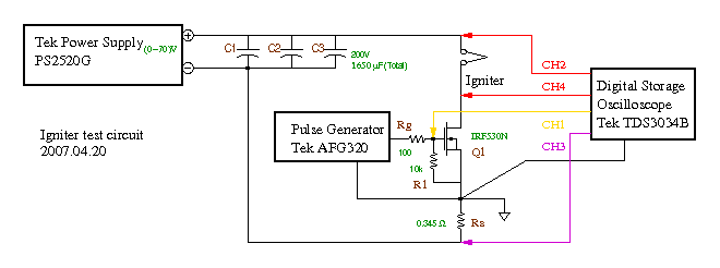
Fig. 2
During testing the pulse generator was manually operated in single pulse mode. Voltage and current measurements were taken at room temperature using a Tektronix TDS-3034B 4 channel digital oscilloscope which we bandwidth limited to 20 MHz. The power supply used for the tests has a 3 A current limit up to 6V, and a 1.5 A limit from 6 to 70 volts.
Testing
Testing at 6 Volts
Test 1
To verify the circuit was operating correctly, the first test used a 1 Ω resistor as a dummy load in place of the igniter. All switching edges were sub-microsecond while overshoot and ringing were negligible. A 131 mA test current, measured by a Fluke 87 multimeter, was passed through the non-inductive, 3W shunt resistor (Rs) and the resulting shunt voltage read off the 'scope was 45.2 mV . The calculated shunt resistance is therefore 0.345 Ω. Finally the supply voltage was adjusted to 6V and igniter #1 was inserted in place of the dummy load.
Test 2
For test 2 (the first firing test) the power supply was adjusted to 6V and the pulse generator set for 250 ms. The match fired, but the bridge wire was left apparently intact. The image captured from the scope is shown in figure 3.
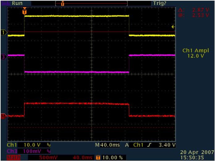
Fig. 3
In figure 3, Ch1 (Yellow) is the gate voltage on Q1, The "Math" channel (in Red) is the voltage across the electric match calculated as Ch2 minus Ch4 (see Fig. 2), and Ch3 is the shunt voltage. The voltage measured across the shunt is negative going as a consequence of our grounding scheme. The figure shows the clean switching waveforms obtained. Since the current through the electric match is almost constant over the entire pulse we can deduce that the bridge wire in the electric match is not fused during the pulse.
The unexpected thing that happened in this firing test is that the bridge wire was not destroyed even though the pyrogen was completely burned. In fact the wire was not visibly damaged.
Test 3
The previous test demonstrated that a Q2 igniter could fire in a reasonable period of time with a 6V power source. For the next test we sought to determine the minimum energy required to fire the igniter. To do this we loaded igniter #3 and applied successive pulses of longer and longer duration.
Pulses of 1, 2, 5, 10, & 20 ms duration had no visible effect on the igniter. When the pulse width was increased to 50 ms a small puff of smoke was seen to rise. When the pulse was increased to 100 ms the igniter fired, looking like a tiny sparkler, all the pyrogen appeared to be consumed.
Test 4
The data from test 3 was suggestive of a minimum firing energy, but to be sure, more data was needed. In test 4 we loaded igniter #5 and pulsed it 3 times at each pulse duration, successively increasing the duration of the pulses in each round.
For pulses shorter than 50 ms no visible changes were detected. However once we reached 50 ms there was a visible puff of smoke emitted at the 2nd and 3rd pulse applications. We proceeded to pulse the igniter 7 more times for 50 ms each, a total of 10 pulses, but no further smoke was seen. We then increased the pulse duration to 66.7 ms and pulsed the igniter 10 more times. We saw smoke on pulses 3-10. In all we saw puffs of smoke during 10 total pulses. Though it seemed plausible that so much pre-abuse of the igniter would influence it's firing energy, this igniter fired perfectly on the first pulse when we increase the pulse duration to 100 ms. Just as in the previous test.
Test 5
As a final low voltage test, we loaded igniter #4, the "bad" igniter identified during the DC resistance tests. This igniter also fired immediately when given a 100ms pulse.
Summary of low voltage testing
Of the 4 tested igniters, all fired at a pulse duration of 100ms. Of the 4 fired igniters, 2 were tested at shorter pulse widths. The first failed to fire at a pulse width of 50 ms, the second failed to fire even when the pulse width was 66.7 ms. Both igniters still fired flawlessly when pulsed at 100 ms.
Oscilloscope data taken during the firing tests indicate that the voltage and current during the pulse was substantially constant. Multiplying the voltage and current measured during the pulse by the pulse duration gives the firing energy. Here is the data
|
Test# |
2 |
3 |
4 |
5 |
|
Igniter# |
1 |
3 |
5 |
4 |
|
Pulse Duration [ms] |
250 |
100 |
100 |
100 |
|
Voltage [V] |
4.2 |
4.1 |
3.5 |
3.5 |
|
Current [A] |
2.9 |
2.9 |
2.9 |
2.9 |
|
Measured Resistance [Ω] |
2.5 |
2.6 |
2.7 |
47.9 |
|
Calculated Resistance [Ω] |
1.4 |
1.4 |
1.2 |
1.2 |
|
Firing Energy [J] |
3 |
1.2 |
1 |
1 |
Table 2
The data in table 2 is interesting. Despite the odd DC resistance we measured for igniter #4, the resistance calculated from the firing test is perfectly reasonable. The good news is that the minimum firing energy for all igniters is fairly consistent at about 1 joule.
The data from the low voltage tests can also be used to estimate the no\[Dash]fire energy. Based on test 4 the no\[Dash]fire energy is around 2/3 the firing energy, that is 700 mJ.
Testing at 70 Volts
Based on our previous experience, we hypothesis that the firing of an electrically actuated pyrotechnic igniter such as the Quest Q2 occurs when a certain definite electrical energy is deposited, independent of the rate at which that energy is deposited. The physical explanation for this phenomenon is that, assuming the pulse is sufficiently short, very little of the energy has time to thermally diffuse out of the device, therefore almost all the energy in the pulse must go to raising the temperature of the device. Chemically, once the interior of the device reaches a certain temperature, the firing reaction is initiated.
To demonstrate that this theory is useful for the Q2's we increased the supply voltage to the limit of our power supply, which is 70 V. The resulting current is in the 40 A range. If the firing energy hypothesis is correct, the minimum firing energy should stay approximately the same, even though the ignition power is over one hundred times greater.
Test 6
To verify proper circuit operation at 70 V another run was made with the 1 Ω resistor as a dummy igniter. The captured waveforms from this test are shown below
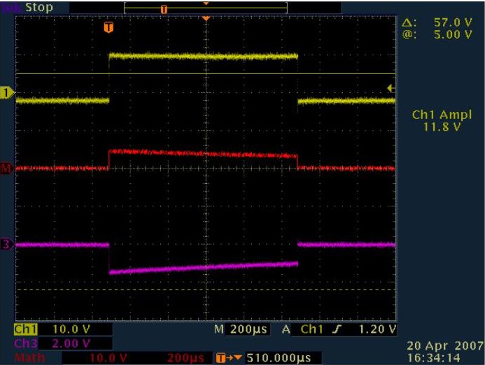
Fig. 4
Figure 4 illustrates the voltage sag which results from the rather high current (46 A) coupled with the fairly small circuit capacitance (1650 μF nominal). Despite the sag, the waveforms are clean, and approximately of constant slope.
Test 7
For this test we used igniter #10. The pulse duration was 1 ms. The igniter fired, but the bridge wire was still unfused.
Test 8
To measure the minimum firing energy at 70 V we loaded igniter #11 and tried successively longer pulses starting from 50 μs. At 250 μs we saw a puff of smoke. At 500 μs the igniter fired. The sparkler pattern of the ignition was visually similar to the low voltage tests. The bridge wire remained un-fused.
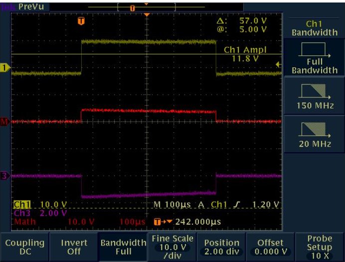
Fig. 5
Test 9
This test was another dummy load. The pulse width was adjusted to 5 ms, the supply voltage is still 70 V.
Test 10
Igniter #8 was fired with a 5 ms pulse. The bridge wire did fuse, but no capture was made.
Test 11
Finally, igniter #9 was fired and a capture made, see below
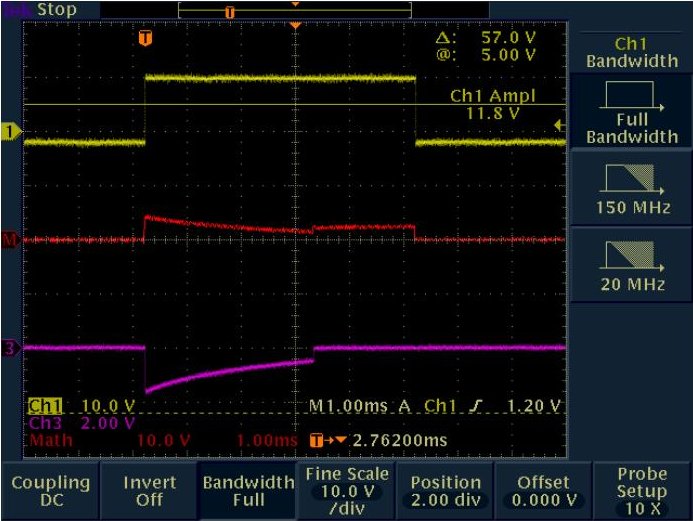
Fig. 6
In figure 6 the small step which occurs about 3 ms into the pulse, is the bridge wire fusing. Once the wire fuses, the current (channel 3) drops to zero.
Analysis
Using test 8 the minimum firing energy at 70 V can be estimated. Taking average values for voltage and current the firing energy for test 8 is
- (1) 40 V * 40.6 A * 500 μs = 0.8 J
This energy is consistent with the low voltage tests given the accuracy of the measurements. Also the theory predicts that shorter pulses have lower firing energies due to reduced thermal diffusion.
Like wise, using data from test 11 the fusing energy can be calculated.
- (2) 30 V * 29 A * 3.6 ms = 3.1 J
Conclusion
Although the testing we did was fairly minimal, our data supports a reasonable expectation that the firing energy of the Quest Q2 igniters is around 1 joule. The fusing energy is substantially higher, around 3 J.
Though the Q2's proved to be surprisingly reliable in the firing tests, there are some definite problems with using them for high reliability ignition systems. The fragile pyrogen and bridge wire are unprotected and easily damaged. The resistance variations observed were quite large, and unexplained. It's likely that high resistance igniters, such as igniter #4, suffer from intermittent open circuits, though this is unproven. Finally the Q2's have only ~1" long leads. Typical high reliability igniters come with factory crimped leads long enough to reach back to the ignition circuitry without splices. Generally this enhances reliability.
Compared to some competing products the Q2's are large and power hungry. Though the ignition heads themselves are fairly small, the glass bead is located so far away from the head that the overall igniter length is still almost 2 inches. This is a major drawback in space critical applications.
Despite the problems. Quest Q2's could probably be used in a high reliability system providing the units were pre-selected for proper resistance tolerance and mechanically protected from shock and lead stress. Even so, better products do exist on the market. The chief advantage of the Q2 over its competitors is ready availability. Many retail hobby shops stock the Quest Q2.