LV2c Nosecone
The nosecone for LV2c, is an optimal design based on the Parker profile. Our particular nosecone is optimal at a velocity of Mach 3. The profile is similar to the Newton shape, but a bit fatter. The Newton shape is derived using a hypersonic (ballistic) approximation. Parker, in contrast, accounts for interaction between the gas molecules using a slender body approximation.
The plug designs for the nosecone are shown below.
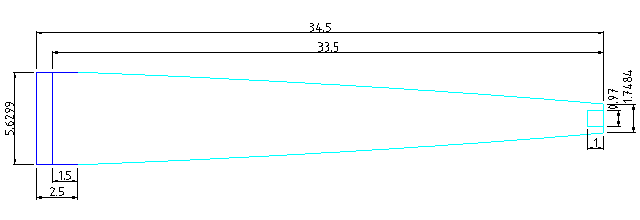
The apex of the nosecone on LV2c is removable and interchangeable. It threads into the nosecone base via standard c-mount thread. The apex uses a straight taper with a rounded tip rather than following the optimal profile. The drag difference is negligible because the of the small radius.
The source drawing for the images shown above is available in PDF format as well in source (DXF) format.
The tip of the nosecone threads into the main section via C-mount thread (1"-32). The exact C-mount specifications can be found on page 30 of this Mitutoyo document.
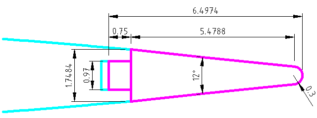
The base-end of the nosecone has a threaded aluminum ring (the tip ring) embedded in the narrow end. The dimensions for this ring are included in the DXF drawing above, but a detail of the tip ring appears below.
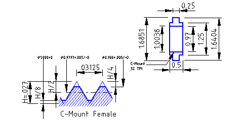
The tip ring detail is extracted from the DXF drawing, but for convenience, it is also given here in PDF format.
Attachments:
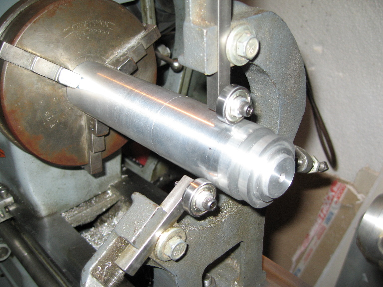
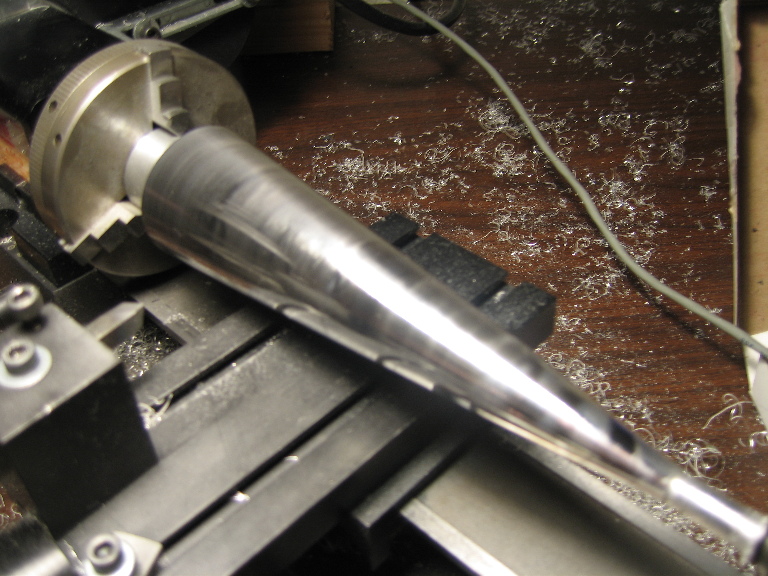
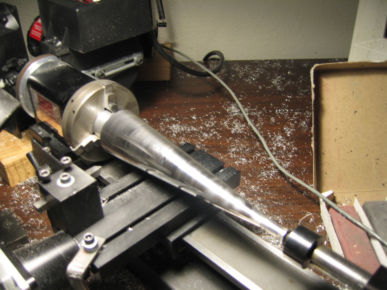
Videos of turning the nosecone on the lathe:
- Nosecone Turning noseconeTurning1.avi
- Nosecone Turning noseconeTurning2.avi
- WoodNosecone1.avi
- WoodNosecone2.avi
Pictures
Nosecone Tip Fabrication


- Below is pictures of edge cleanup and hole drilling/countersinking of the nose cone, similar to stuff we had done before.

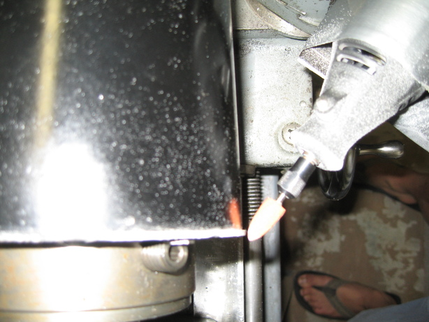
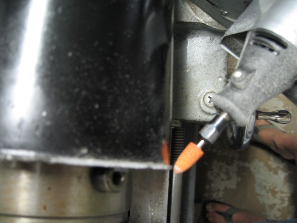
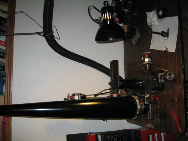
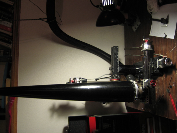
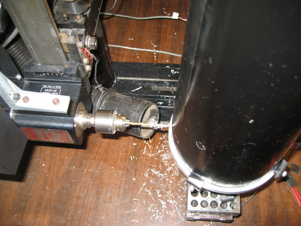

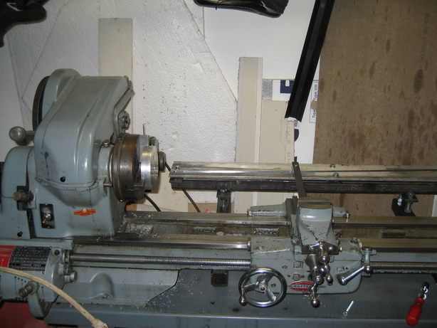
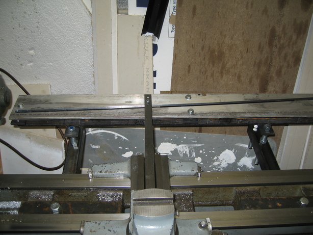
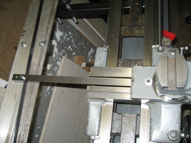
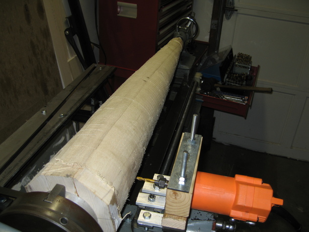
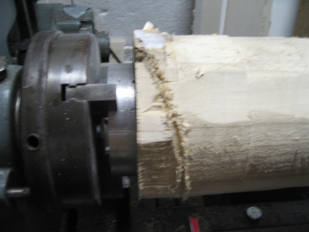
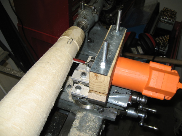
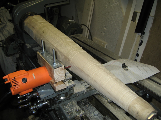
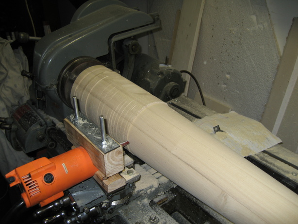
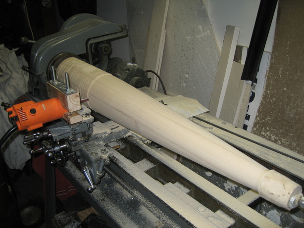
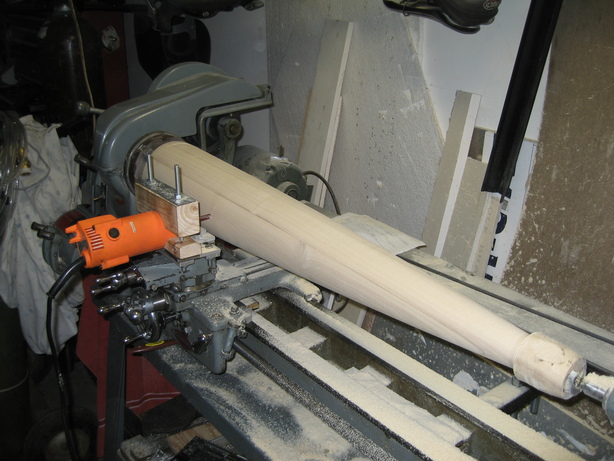
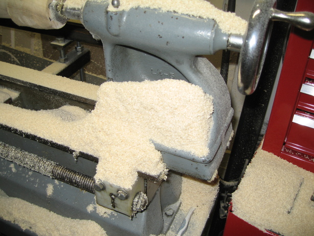
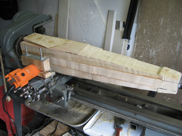
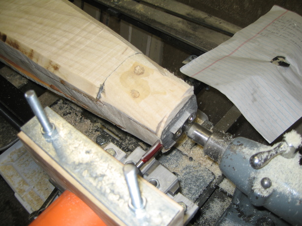
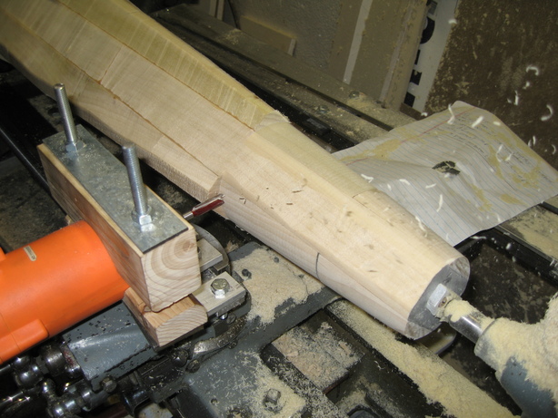
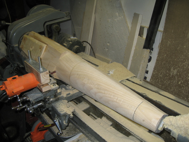
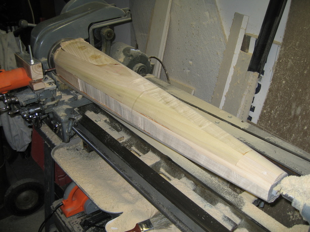
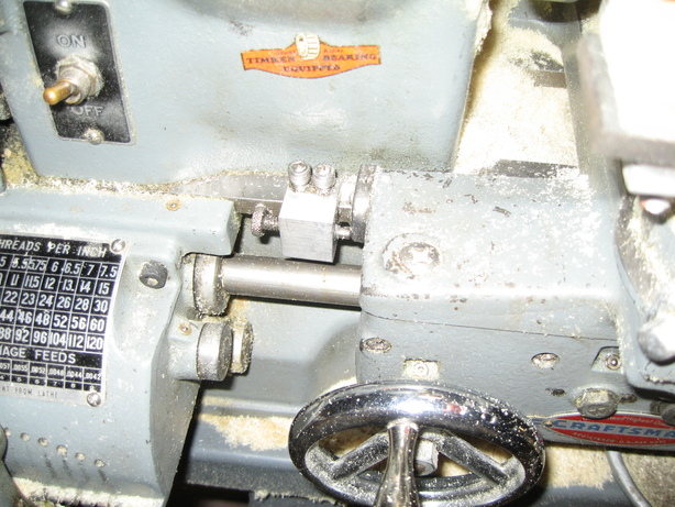
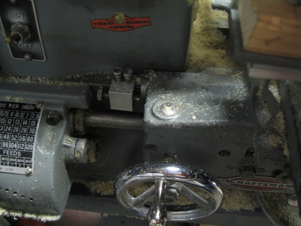
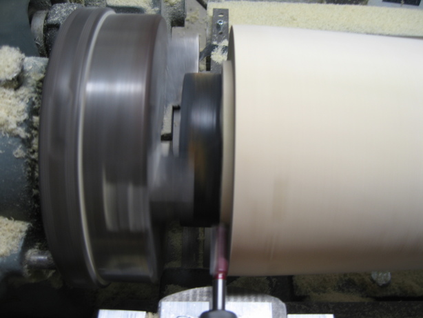
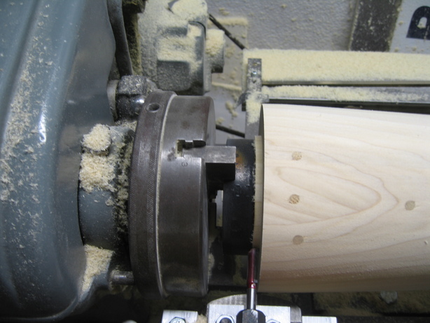
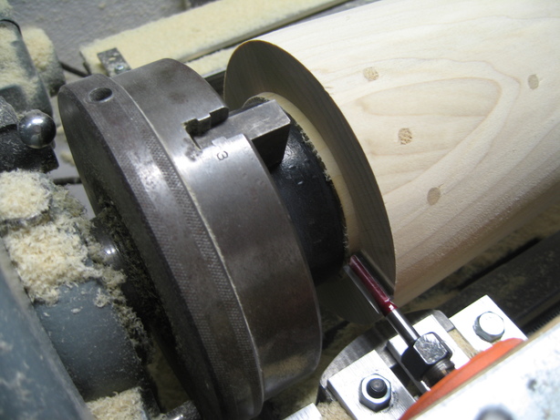
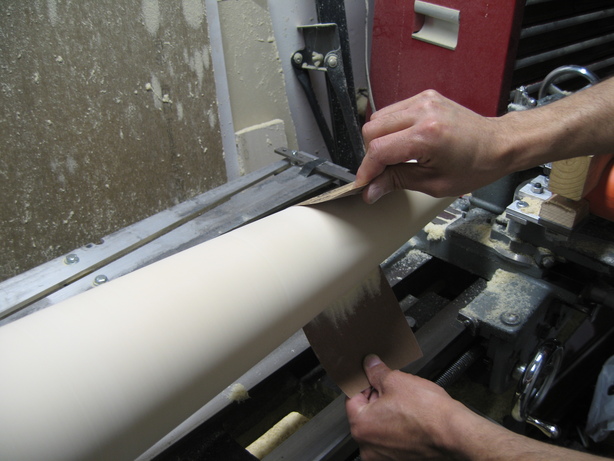
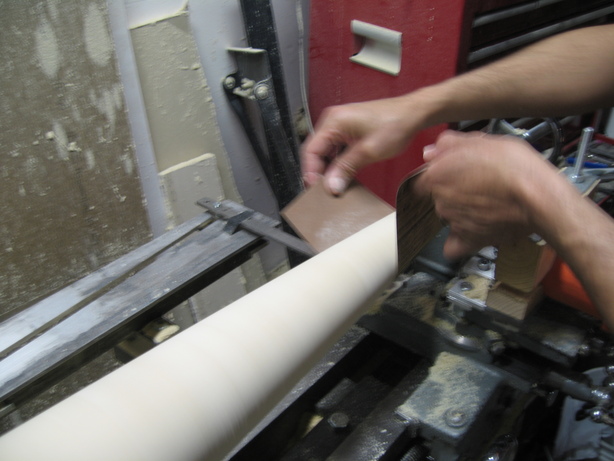
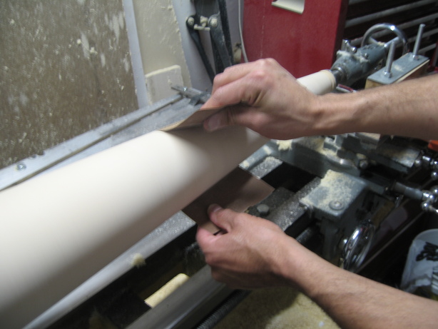
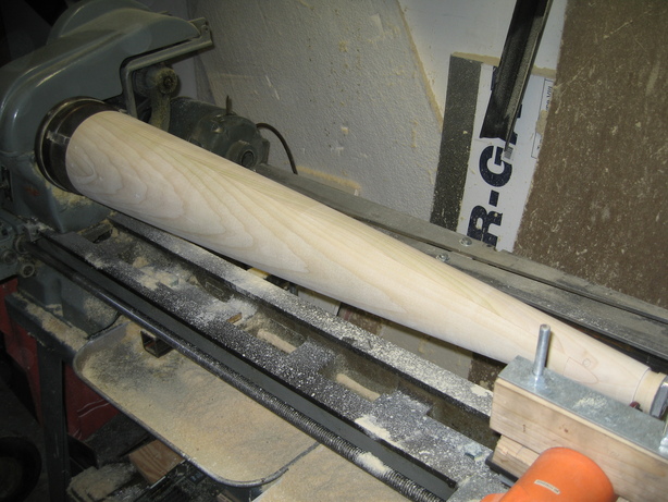
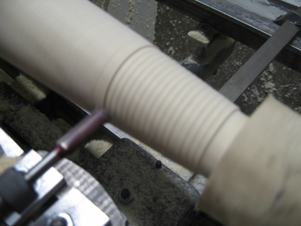
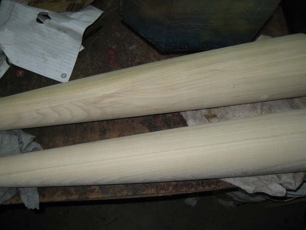
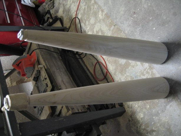
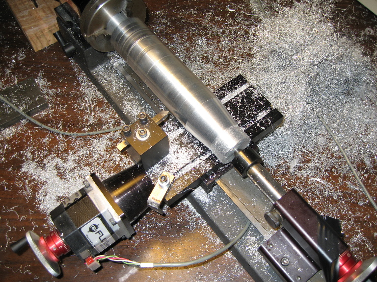
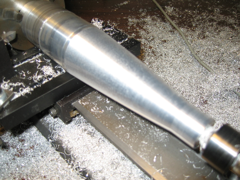
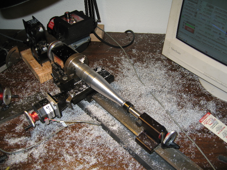
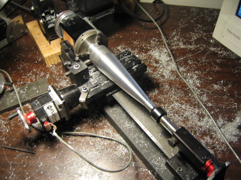
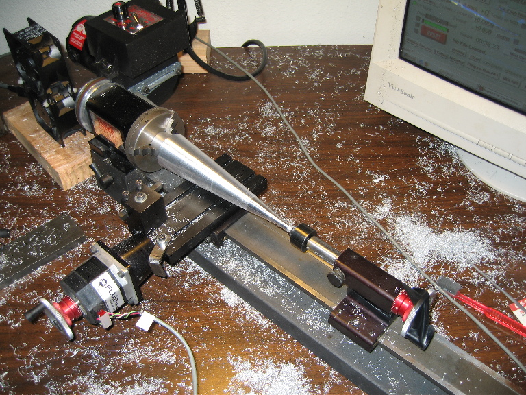
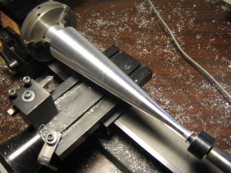
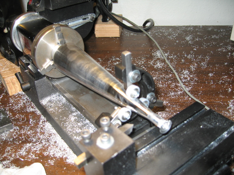
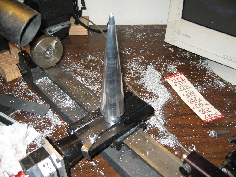
Mold Making
Below is are pictures of a "passive CNC" technique we used to get the proper profile for our nosecone out of a normal manual lathe. The results turned out quite nice, especially with the router on there. Made for a very smooth contour, which we will still sand down. We used popler wood for this, glued together from multiple blocks with (insert type of glue here). You'll notice that on one end is a nice long diagional gouge, that's from trying to use an 1/4" endmill during testing. Bad, the flutes are too tight and the helix tends to screw itself into the wood. Instead, use a normal straight edge router bit. We removed the cross slide nut from under the cross slide and mounted a piece of flat bar where the cross slide nut screwed into, then there was a bearing on the other end that fit snugly into the slot of the guide. The route was a cheepie harbor freight laminate trim router, so it was fast, but didn't have much torque. We had to keep the power feed kind of slow and our plunge at less then 0.100", other wise you could hear the router start to get loaded. Also of interest, there are to thick wall square tubes mounted to the lathe, going to the back side, with 1/2" holes in them. Above that is a cross square tube with some plates welded to them (you could easily use counter sunk screws if you wanted). Anyways, you'll notice the 1/2" threaded rod, with 1/2" nuts on top/bottom of the lower square tube, and top/bottom nuts on the side plates. This gives you the ability to adjust the height of the whole assembly and level the plate. Kind of important if you want to reproduce this setup.