ATV Can Node
It's a PIC16F877 + SJA1000 "MISC" PCB modified to use a PIC18F458 running at 20MHz. It also has the following pin hooked up to the ATV distribution board:
| Pin | # | Goes to: |
|---|---|---|
| RC6/TX | 44 | BOB-II UART in |
| RC2/CCP1 | 36 | Power level |
| RD0 | 38 | Red LED |
| RD1 | 39 | ATV transmitter IPS511s feedback pin |
| RD2 | 40 | ATV transmitter IPS5451S input (ATV TX power on/off) |
| RD3 | 41 | Overlay board IPS511s feedback pin |
| RD4 | 02 | Overlay board IPS511S input (overlay board power on/off) |
| RD5 | 03 | Camera IPS511s feedback pin |
| RD6 | 04 | Camera IPS511S input (camera power on/off) |
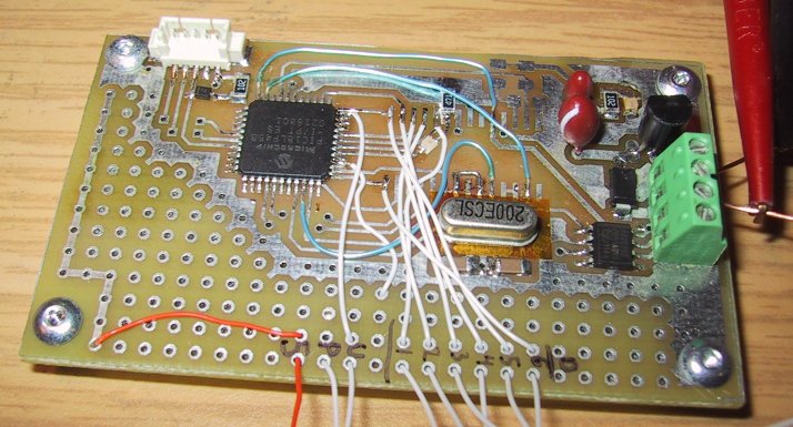
U = UART, P = PA power level, 5 = 5V (orange), 1 - 6 is the PIC pin number (RD1 - RD6). Note that the wires dive through the holes for strain relief.