PSAS Request for Antenna Design Assistance
 |
Introduction
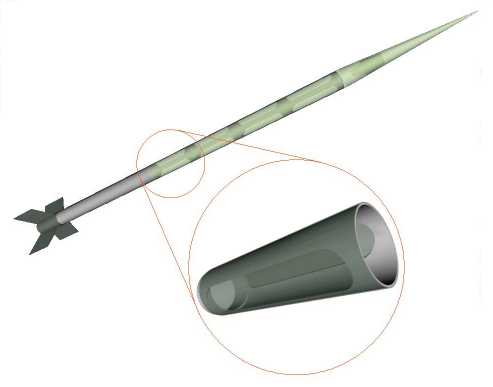
The Portland State Aerospace Society (PSAS) is a university-based non-profit group located at Portland State University in Portland, Oregon. We're currently working on our third generation sounding rocket called Launch Vehicle No. 2 - or LV2. LV2 is 3.5m tall (11.4ft), 13.6cm (5.37") in diameter, and should obtain a maximum velocity of Mach 3.5 on it's way to an apogee of 20km (65,600ft). Here's the PDF file of the simulated flight profile.
We're scheduled to launch a low altitude airframe test on September 29th, and possibly a half height flight the day after. Our next launch will be sometime in Spring 2002.
Our eventual goal is to do active guidance using inertial sensors - i.e., inertial navigation. To that end, LV2 is outfitted with a 586-class Flight Computer, our own inertial measurement unit, and a GPS unit. For more information on our project, please see our web page at http://www.psas.pdx.edu/.
Everything is going extremely well on LV2, except for one thing: antenna design. Although many of us are amateur radio operators, we have very little experience in microwave and/or specialized antennas.
LV2 requires three antennas:
- A 2.4GHz antenna for our bidirectional telemetry link (we're using 802.11b Channel 1 which is at 2.422GHz with a bandwidth of about 20MHz)
- A 1.5GHz receive antenna for the GPS unit (1.57542GHz)
- A 1.3GHz broadcast antenna for the amateur TV broadcasting board which will beam down live images of the rocket in flight (1.277GHz with a bandwidth of about 6MHz).
If we had an RF department which specialized in antennas here at PSU which focussed in antennas, we obviously wouldn't have a problem. Unfortunately, we don't, so we desperately need outside help with these systems. In particular, we're hoping to find someone or someones who would be willing to help us design the antennas, or at least point us in the right direction.
Below is a discussion of our design issues.
Desired Antenna Radiation Pattern
Ideally, the radiation patterns for our antennas would be:
The 1.5GHz GPS antenna would have slightly more than a half sphere pointing directly up the rocket. This would provide coverage for the entire sky, improving our chances of locking on to the GPS satellites.
The 2.4GHz telemetry and 1.3GHz ATV broadcast antennas should have a single lobe pointing straight down. The receive antennas are placed almost directly under the rocket near the launch tower, and we expect the rocket to travel straight up (+/- 20 degrees). More coverage would certainly work (e.g., a half sphere) but obviously the wider the coverage the less gain we get from the antenna. Of course, we'll take what we can get: if we get an omnidirectional antenna that works, heck, we'll take it.
The Big Problem: Antenna Placement
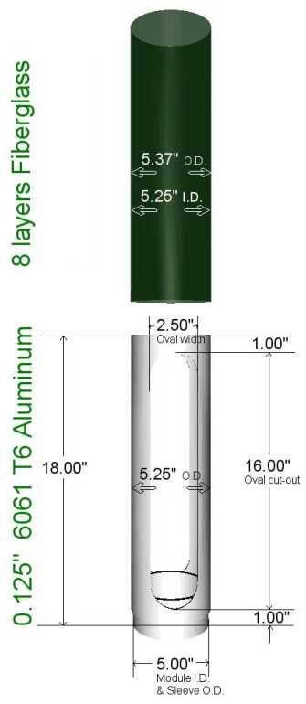
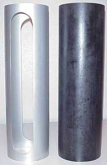
LV2 consists of modular airframe pieces which bolt together. The Avionics module bolts directly on top of the propulsion module (the solid rocket motor), and then our payload, recovery system and nosecone bolt on top of it. The airframe sections are Alumninum cylinders with two 2.5" ovals cut out to decrease weight. Around the Al airframe is a fiberglass (8 layers of E glass) aeroshell.
Here's a diagram of exactly what we have:
|
|
|
 |
 |
We don't think we can put our antennas in the nose, since the nose will be ejected at apogee to release the parachutes. Although we are tethering the nose cone, we want the antennas to work after apogee - and the nose cone will probably end up wildly oscillating on the end of the tether.
We also don't think we can put our antennas on the fins, since the fins are Aluminum and are on a detachable fin canister that slides over the rocket and rests on a lip on the bottom of the motor. Even if we had some sort of connecting system, the fins are made of thin Aluminum and thus essentially giant ground planes... and in the future, we hope to eliminate the fins all together when we move to inertial navigation.
We've identified a few possibilities, in the order we feel is best to worst:
1) Multiple, or Cylindrical, Patch Antennas
A cylindrical patch antenna - or many ganged patches - would be low profile and seems like once the sizing of the patch(es) has been determined, it should be fairly easy to build. We could even use the Aluminum shell as the ground plane to make it even thinner.
The only real problem with a cylindrical antenna is that we get a toroid radiation pattern with a null pointing straight down (exactly where our ground antenna will be located). We thought of using two rings and attempting to phase them in such a way as to point the radiation pattern down towards the ground... but we have no idea if that would work.
2) Slot antennas located in the oval slots in the Aluminum frame which radiate through the fiberglass
After exploring antenna types, we realized that we could integrate slot antennas into the oval slots in the Aluminum frame. Although the ovals are the wrong size for the wavelength, we could easily "fill in" the oval with copper in order to make the correct sized slot. The problem is that we have a hybrid cylindrical/planar antenna. We can't just make a cylindrical slot antenna because we have metal "junk" - the avionics system - in the cylinder. But we're not sure we can use the slots as a planar slot antenna because the cylinder drops back unlike the usual ground plane on a planar slot antenna.
3) Patch or microstrip antennas located in the oval slots in the Aluminum frame which radiate through the fiberglass
We would locate two patch or microstrip antennas as close to the fiberglass skin as possible in each of the oval slots, and end up with what would probably be a two lobed radiation pattern.
Request for help
We desperately need help designing this antenna system. If you're interested in antennas for aerospace, or just interested in antenna design in general, we encourage you to contact us and give us a hand. Even emailing us with advice would be extremely helpful.
Also, if you design antennas on a commercial basis, any donated designs can be tax deductible (via our 501C3 status). Finally, we are also able to use some our grant monies to purchase antennas, but these funds are unfortunately very limited.
Please contact Andrew Greenberg at (503) 788-1343, or email AndrewGreenberg, to help.
Thanks,
The PSAS Avionics Team