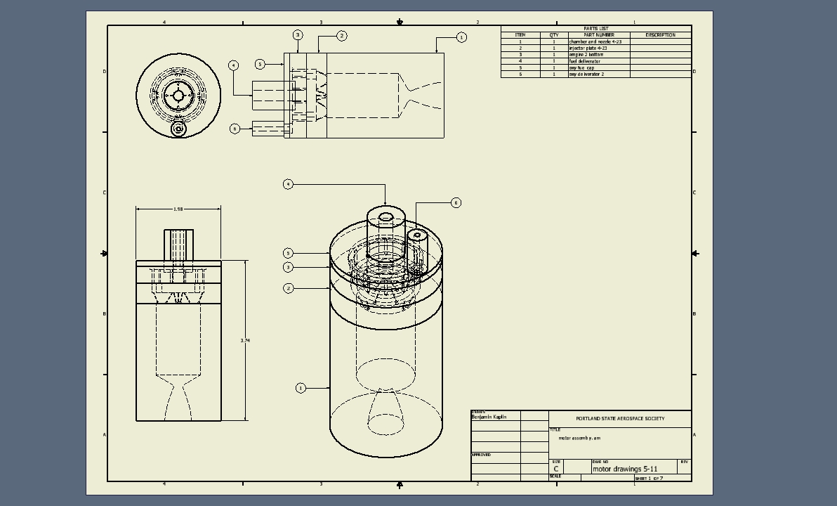
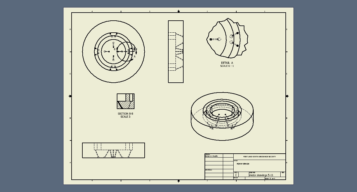
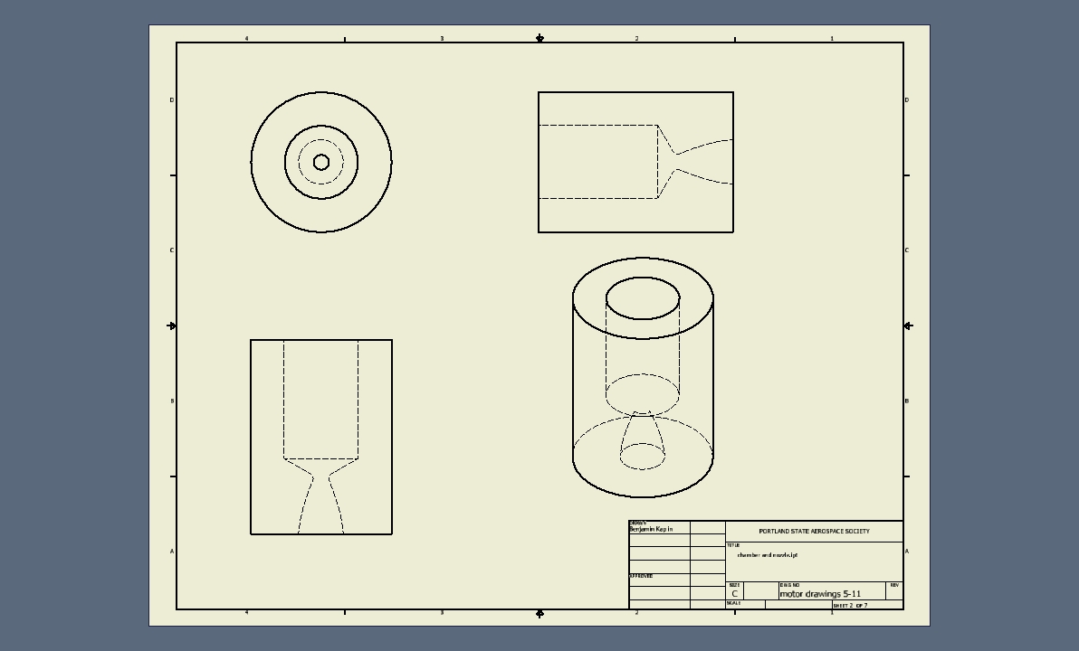
Renders (5/4/02011)
Plan of Attack
- Finalize Injector Design
- Injector Design Review
- Fabricate injector
- Test injector flow rate
- Do lots of estimates re: differences between flow characteristics of test fluids and production fluids
- Adjust engine parameters to match injector flow characteristics
Current Issues List
- Identify separating forces in Emperor fuel-delivery system
Injector Element Design
It has been shown elsewhere (and examined to the satisfaction of Propulsion Team members) that a liquid flow resulting from the impingement of two jets directly opposed will flow axially down the chamber if the following holds:

where  and
and  are the angles between the chamber axis and the fuel and oxygen flows respectively.
However, because we are working with a three-port injector element, the radial mass flows are not necessarily so simple. We can rewrite the above equation to account for the additional angle like so:

A common injector parameter is the angle between the streams of oxygen and fuel flow in the plane of fuel flow. The value we have found and are designing from for this parameter is sixty degrees. We can describe the triangle formed by the fuel stream impingement angles and the angles at which the streams leave the injector plate like so:
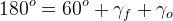
Choosing  arbitrarily, we can solve algebraically to show that
 can be derived from trigonometric and algebraic manipulations on the 3 port injector element maths above. The derivation is left as an exercise to the reader, but the final result is as shown:
![\gamma_z = cos^{-1} \left[\frac{\overset{\centerdot}{m_f}v_fcos(\gamma_f)}{2\overset{\centerdot}{m_o}v_ocos(\gamma_o)} \right]](./25202fa07758ae9b30b877ae3c308f63.png)
There are not-immediately-obvious singularities to avoid, but the values of gammaf and gammao set equal to 60o work well.
Engine Parameters
5/1/02010:
Engine
| Characteristic | Value |
|---|---|
| Thrust | 72.779 |
| Mass Flow | 0.0917 kg/s |
| Chamber Pressure | 6.895e6 Pa (1 ksi, 68.05 atm) |
| O/F Ratio | 2.29 |
| Ratio of Specific Heats | 1.22 |
| Adiabatic Flame Temperature | 3525 K |
| Molar Weight of Gases | 21.6 |
| Exit Velocity | 2831.7 m/s |
| Combustion Chamber Volume | 1.7393 ( in3) |
| Throat Diameter | 5.49 mm (0.2161 in) |
| Exit Diameter | 16.1 mm (0.6323 in) |
Injector
| Characteristic | Value |
|---|---|
| Elements | 4 |
| Fuel Hole Diameter | .344 mm (0.01354 in) |
| Oxygen Hole Diameter | .338 mm (0.0133 in) |
| Fuel Stream Impingement Angle | 22.5o |
| Oxygen Stream Impingement Angle | 13.19o |
Injector Plates
Some random note on this:
Pressure drop across injectors - Typically 15-25% of chamber pressure. High pressure drops increase stability (RPE p.284). Seems logical. Some sources cite delta p across injector ~41% of chamber pressure to further reduce feed system induced combustion instability.
Angle of injection - Set to get axial flow after impingement, based on mass flow and angle. i.e. "Resultant momentum at the point of impingement between the fuel and oxidizer flow is axially directed"
What is a good injection velocity? One publication cited a study of 5 m/s up to 50 m/s, over a range of chamber pressures, vs. stability. Less than 18-20 m/s cited stability issues. This is likely due to fuel entering the chamber at speeds less than that of the flame front.
Types:
- Coaxial injection
- Like On Like (LOL) Fuel impinges on Fuel, Ox on Ox.
- LOX on Fuel Impinging (armad?)
- Fuel Ox Fuel impinging (FOF) only seen with LH2 and LOX (Empirical Google presence)
- OFO Presumed higher efficiency, at expense of stability
Preliminary design parameters
delta P (injector) = 41% of Pc
Injection velocity = 30 m/s
Injection type: OFO
Impingement angle = Fuel: 45 deg.; Oxygen: 11.8586 deg.
Pre-Impingement distance = 5 mm
Orifice L/D ration = 18.4 or 80 (decide this)
Preliminary Flow Calculations
O/F ratio =~ 2.35
RPE (277):
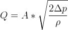
Rearranging allows us to solve for total hole area in injector plate satisfying desired fuel flow and oxygen flow:
Ao = 1.158 E-6 m^2
Af = 6.123 E-7 m^2
The new script version computes these values and more, including from an input of number of impingement elements, the individual hole sizes.
Topics for discussion
- Friction and surface tension effects along length of injector holes.
Useful Mathematical Relationships and Information:
Notation Guide
| Symbol | Meaning |
|---|---|
 |
Specific Gas Constant, Gas Constant. |
 |
Mass flow (combined fuel and oxidizer). |
 |
Cross-sectional area at a point in the engine. |
 |
Gas velocity at a point in the engine. |
 |
Gas specific volume. |
 |
Gas pressure. |
 |
Temperature. |
 |
Subscript denoting engine chamber. |
 |
... engine throat. |
 |
... exhaust exit. |
 |
... ambient pressure. |
 |
Gravitational acceleration. |
 |
Ratio of specific heats at constant pressure and volume. Thermodynamic constant for specific gases. |
 |
Thermal efficiency of the motor. Function of pressure and temperature ratios. |
 |
Mach number (dimensionless ratio of speed to local speed of pressure wave propagation). |
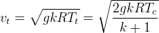
Formulae
 where
where is the universal gas constant and
 the average molecular weight of the exhaust gases which can be found here: http://www.braeunig.us/space/comb.htm.
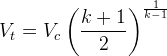
 (RPE 3-24)
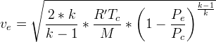
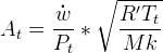
 (RPE p. 52). This equation gives optimum fuel consumption as a function of thrust and exhaust speed c.
 (RPE 3-23)
![N_m^2 = \left(\frac{2}{k-1} \right) \left[\left(\frac{P_c}{P_e}\right)^\frac{k-1}{k}-1 \right]](./f43f88950ac7b2b6f46332cbe4bc4589.png) (http://www.braeunig.us/space/propuls.htm 1-29)
(http://www.braeunig.us/space/propuls.htm 1-29)
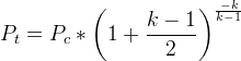
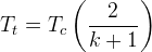 (RPE 3-22)
 (RPE 3-21)
 (Isentropic compression? Sourced from http://www.braeunig.us/space/sup1.htm)
 (Ideal Gas Law)
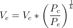 (RPE 3-6 and p. 52)
 (RPE 3-24)
 (Braeunig 1.26)
![A_e = \frac{A_t}{N_m} * \left[\frac{1+\frac{k-1}{2}*N_m^2}{\frac{k+1}{2}} \right]^\frac{k+1}{2*(k-1)}](./35767520ed50023581ff84f5ddd9d260.png) (Braeunig 1.30)
(Braeunig 1.30)
References
Liquid Rocket Engine Combustion Instability by Vigor Yang, Yang, William E. Andersen (Editor)
Rocket Propulsion Elements by George P. Sutton, Oscar Biblarz
Spray Characteristics of Impinging Jet Injectors at High Back-Pressure